บริษัท เอดีดี เฟอร์เนส จํากัด
ADD FURNACE CO.,LTD.
44 ซอยบรมราชชนนี 70 ถนนบรมราชชนนี แขวงศาลาธรรมสพน์ เขตทวีวัฒนา กรุงเทพฯ 10170
โทร: 02-888-3472 โทร: ออกแบบ:08-08-170-170 แฟกซ์: 02-888-3258
https://www.add-furnace.com E-mail: sales@add-furnace.com
INSTALLATION
CAUTION
1.
Installer must be a trained, experienced flam
safeguard control serviceman.
2.
Disconnect power supply before beginning
installation to prevent electrical shock and
equipment damage.
3.
All wiring must comply with applicable local
electrical codes, ordinances, and regulations.
4.
Voltage and frequency of power supply connected
to this detector must agree with the values
marked on the detector.
6.
On multiburner installation, each detector must
respond only to the flame(s) produced by the
burner it is supervising.
7.
Do not connect more than two detectors in parallel
to a single R7061 or R7861A Dynamic Self-Check
Ultraviolet amplifier.
8.
Perform all required adjustments and check- out
tests after installation is complete.
Install the Sight Pipe
After you have determined the location and sighting angle, select
the sight pipe. A black iron pipe with a diameter of at least 1-1/2 in.
(38.1 mm) is recommended. Do not use stain- less steel or
galvanized pipe because they reflect ultraviolet radiation internally
and complicate aiming the pipe.
Sight pipes with diameters 2 to 3 in. (51 to 76 mm) produce better
results for horizontal rotary burners, which require wide viewing
angles. A wide viewing angle can also be obtained by using a
short sight pipe.
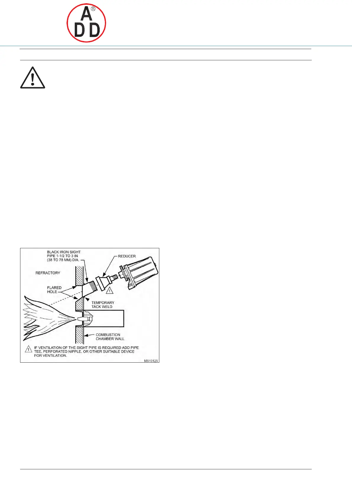
Fig. 5. Typical mounting of C7061A/F
Prepare Hole in Wall of Combustion Chamber
Cut or drill a hole of the proper diameter for the sight pipe in the
wall of the combustion chamber at the selected location.
Flare the hole to leave room for small adjustments of the sighting
angle. The taper of the hole should be about 1 in. for every 3 in.
(25 mm for every 76 mm) of Wall thickness.
Mount Sight Pipe
Thread one end of the pipe to fit the mounting flange, union,
or required coupling. Cut the pipe to the desired length (as short as
practical) and at an angle so it fits flush with the wall of the
combustion chamber. Tack- weld the pipe to the wall in a trial
position. Do not weld the sight pipe permanently in place until
after completing the Adjustments and Checkout.
Install Fittings
In some cases, the sight pipe does not directly fit the C7061A/F
mounting flange or union. Also, it may be desirable or necessary
to ventilate the sight pipe. You may also want to use a swivel
mount or an antivibration mount. Each of these cases may require
additional fitting.
Reducer
For sight pipes of larger diameter than the mounting flange
connector or union, install a reducer as illustrated in Fig. 5. The
reducer will require a close nipple with these external threads: 3/4
or 1 inch. NPT.
Sight Pipe Ventilation
It may be necessary to ventilate the sight pipe to cool the detector
or to clear a viewing path through UV radiation attenuating
material.
For a negative pressure combustion chamber, drilling a few holes
in the section of the sight pipe outside of the combustion chamber
will allow air at atmospheric pressure to flo w through the sight
pipe and into the chamber. A perforated pipe nipple between the
sight pipe and the detector can also be used.
For a positive pressure combustion chamber, connect a supply of
pressurized air from the burner blower to flow through the sight
pipe and into the chamber. The air pressure must be greater than
the chamber pressure.
Swivel Mount (C7061A only)
To facilitate proper flame sighting, use part no. 118367A Swivel
Mount (not supplied). The swivel mount requires a reducer of the
proper size to mount it onto the sight pipe. It also requires a
one-inch close nipple for mounting to a C7061 with a one-inch
connector. (For 118367A Swivel Mount mounting details, refer to
form 60-0361).
Antivibration Mount
The detector withstands normal burner vibration. If the vibration is
excessive, part no. 123539 Antivibration Mount is available. (For
mounting details, see form 60- 0361). If you use this mount, install
it before positioning and sighting the detector.
Mount the Detector
Mount the detector onto the sight pipe, reducer, or other fit ting.
The C7061A/F Self-Checking flame detectors incorporate an
oscillating shutter mechanism and, therefore, require special
consideration for mounting positions other than vertically sighting
downward or upward, as illustrated in Fig. 6. The C7061A/F has
notch and arrow indicators (see Fig. 7 and 9) on the faceplate to
facilitate mounting in positions other than those shown in Fig. 7.
The notch and arrow must be vertically aligned with the notch in the
up position and the arrow pointing downward (see Fig. 7). The
C7061A/F must be mounted with the conduit opening located
approximately 45 degrees below the horizontal
 Loading...