บริษัท เอดีดี เฟอร์เนส จํากัด
ADD FURNACE CO.,LTD.
44 ซอยบรมราชชนนี 70 ถนนบรมราชชนนี แขวงศาลาธรรมสพน์ เขตทวีวัฒนา กรุงเทพฯ 10170
โทร: 02-888-3472 โทร: ออกแบบ:08-08-170-170 แฟกซ์: 02-888-3258
https://www.add-furnace.com E-mail: sales@add-furnace.com
INSTALLATION AND OPERATION
PLANNING THE INSTALLATION
Proper flame detector application is the back of a safe and
reliable flame safeguard installation. Refer to the burner
manufacturer’s instructions as well to those included here.
Follow all instructions carefully.
CAUTION
1. Do not connect these detectors to non-
Honeywell manufactured controls (primaries,
programmers, multiburner systems, and
burner management systems). Unsafe
conditions could result.
2. Disconnect power supply before beginning
installation to prevent electrical chock and
equipment damage. More than one
disconnects may be involved.
3. All wiring must be NEC Class 1 (line volt-
age).
4. Voltage and frequency of the power supply-
connected to this detector must agree with
the values marked on the detector.
5. Sight the detector so it does not respond to
ignition spark.
6. On multiburner installations, each detector
must respond only to the flame of the burner
it is supervising.
IMPORTANT
Do not connect more than two C7061A/F flame
detectors in parallel.
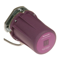
Basic Requirements
The combustion flames of most carbon-based fuels emit
sufficient ultraviolet radiation to enable the C7061A/F Solid
State (Purple Peeper) ultraviolet flame detector to prove the
presence of a flame in a combustion chamber. The
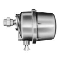
detector mounted outside the combustion chamber. Its
mounting flange or union is threaded to one end of a sight pipe
inserted through the wall of the combustion chamber. The
ultraviolet sensing tube in the flame detector sights the
flame through the pipe.
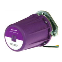
When a flame is present, the UV tube in the C7061A/F
senses the ultraviolet radiation emitted. The C7061A/F pro-
duces a signal that is sent to the amplifier in the flame safe-
guard control. The amplified signal pulls in the flame relay in
the control to allow proper operation of the system.
Because it is necessary for the UV sensing tube to actually
see the flame, it is best to locate the detector as close
to flame as physical arrangement, temperature, and other
restrictions permit. These restrictions are described in detail
in the following paragraphs.
Determine the location
Before beginning the actual installation, estimate the best
location for mounting the detector based upon these factors:
1. Temperature
Install the flame detector where the surrounding
temperature will remain within the specified ambient
operating temperature ratings.
For the C7061A/F, to keep the detector temperature within
specification. If the temperature rating is exceeded, the
introduction of cooling air will be necessary.
2. Vibrations
Do not install the detector where it could be subject of
excessive vibration; it shortens the life of the electronic com-
ponents. Vibrations with a magnitude greater than 1g will
require an anti-vibration mount to cushion the detector.
3. Clearance
Make sure there will be enough room to remove the cover of
the detector for servicing.
Radiation sources other than flame
Examples of radiation sources, other than a flame , which
could actuate the detection system:
Ultraviolet sources
•
Radiant surfaces above 1200°C (2200°F).
•
Sparks from ignition transformers and welding arcs.
•
Gas lasers
•
Sun lamps
•
Halogen lamps
•
Germicidal lamps
•
incandescent lamps held close to the sensing tube
•
Filament above 1200°C (2200°F).
Gamma ray and X-ray sources
•
Diffraction analyzers
•
Electron microscopes
•
Radiographic X-ray machines
•
High voltage vacuum switches
•
High voltage condensers
•
Radioisotopes
Except under very unusual circumstances, none of these
sources, except a radiant surface or ignition spark, would
be present in or near the combustion chamber. The
detector may respond to a radiant surface at a temperature
above 1200°C (2200°F) if both of the following conditions are
present the surface represents a significant percentage of
detector’s field of vi w.
If the temperature or a radiant surface causes the flame
relay (in the flame safeguard control) to pull in, re-aim the
sight pipe so the detector views a cooler area, or the
sensitivity of the detector decreases. Ignition sparks is a
rich source of ultraviolet radiation.

 Loading...