บริษัท เอดีดี เฟอร์เนส จํากัด
ADD FURNACE CO.,LTD.
44 ซอยบรมราชชนนี 70 ถนนบรมราชชนนี แขวงศาลาธรรมสพน์ เขตทวีวัฒนา กรุงเทพฯ 10170
โทร: 02-888-3472 โทร: ออกแบบ:08-08-170-170 แฟกซ์: 02-888-3258
https://www.add-furnace.com E-mail: sales@add-furnace.com
WIRING
CAUTION
When using a C7061A/F with an R7061 or R7861
Dynamic Self-Check amplifier, be careful not to
short the white shutter lead wires together (by
wiring incorrectly, leaving an incorrect jumper wire,
or stripping the insulation too much so the bare
lead wires can touch).
If the shutter lead wires are shorted during the
operation, the amplifier can be permanently
damaged and nonoperative.
1.
All wiring must comply with applicable local
electrical codes, ordinances, and regulations.
Use NEC class 1 wiring.
2.
Keep the flame signal lead wires as short as
possible from the flame detector to the
terminal strip or wiring sub- base.
Capacitance increases with lead wire length,
reducing the signal strength. The maximum
permissible lead wire length depends on the
type of lead wire and conduit type and
diameter. The ultimate limiting factor in flame
signal lead wire length is the signal current.
3.
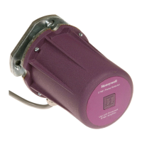
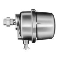
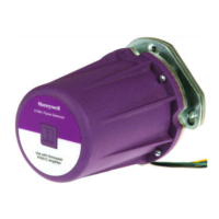
The C7061A/F detectors have a terminal
connection block. The wires must be run in a
conduit.
4.
If the lead wires are not long enough to reach
the terminal strip or wiring subb a s e , make
the required splices in a junction box.
5.
If splicing is necessary, use moisture-
resistant no. 14 wire suitable for at least
75°C (167°F) if the detector is used with a
flam safeguard primary control, or at least
90°C (194°F) if used with a flame
safeguard programming control.
6.
For high temperature installations, use
Honeywell specification no. R1298020 wire
or equivalent for the F lead wire. This wire
is rated up to 204°C (400°F) for continuous
duty. It is tested for operation up to 600 volts
and for breakdown up to 7500 volts. For the
other lead wires, use moisture-resistant no.
14 wire selected for a temperature rating
above the maximum operating temperature.
7.
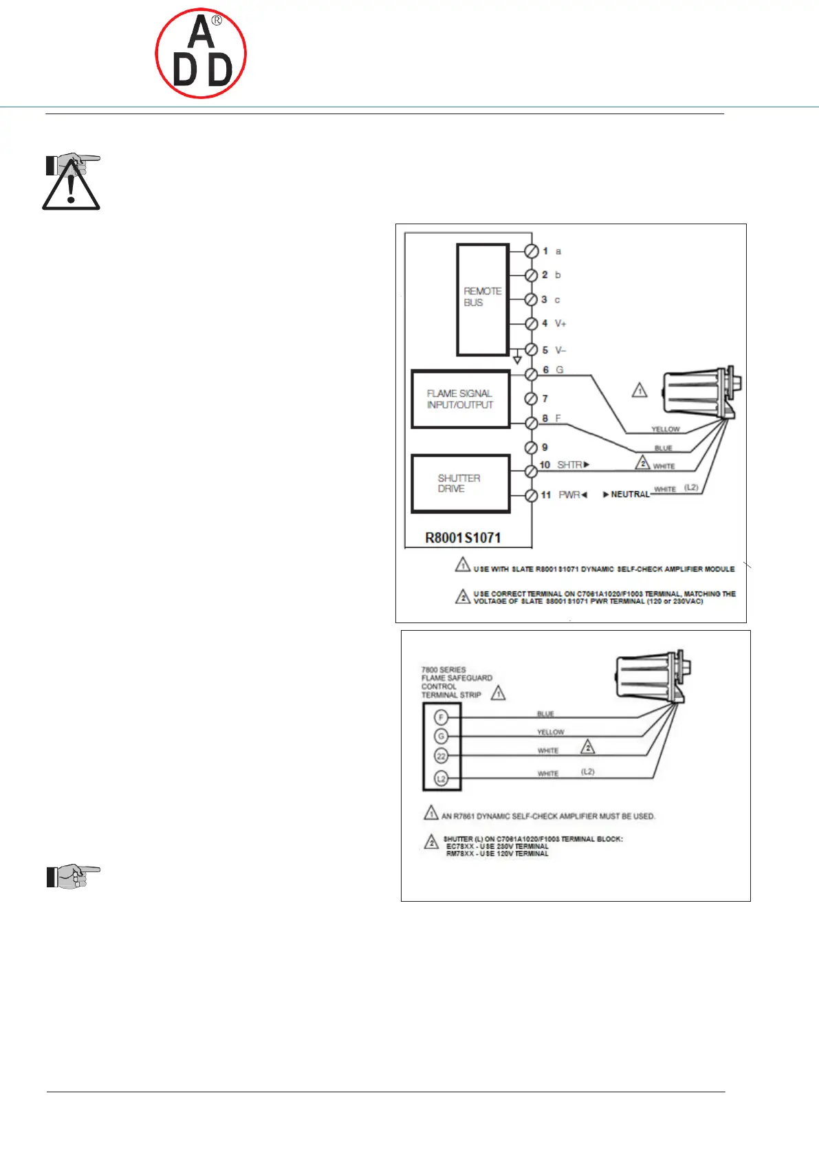
Refer to Fig. 10. for wiring connections
To avoid exceeding the rating of the solid-state shutter
switch in the R7861 flame signal amplifier, do not connect
more than two C7061A detectors in parallel.
IMPORTANT
Voltage and frequency rating of the C7061A
must match the power supply of the flame safe-
guard control.
Fig. 10_1. Wiring diagram for C7061A1020 detectors with
7800 SERIES Flame Safeguard controls with
shutter drive circuitry.
IMPORTANT
Do not run the flame detector wiring in the same
conduit with high voltage ignition transformer
wires.
Connecting Detectors in Parallel
For a flame that is difficult to sight, using two parallel C7061
flame detectors reduces nuisance shutdowns. If only one of
the parallel detectors loses the flame signal, the other
indicates the presence of the flame and keeps the burner
running. If two parallel C7061A detectors are used, a
flame simulating failure in either detector causes the
burner to shut down. Two C7061A detectors can be
connected in parallel to the same terminals on 120-volt
flame safeguard controls.
Fig. 10_2. Wiring diagram for C7061A/F detector with
SLATE, refer to the SLATE Instruction Sheets.
 Loading...