บริษัท เอดีดี เฟอร์เนส จํากัด
ADD FURNACE CO.,LTD.
44 ซอยบรมราชชนนี 70 ถนนบรมราชชนนี แขวงศาลาธรรมสพน์ เขตทวีวัฒนา กรุงเทพฯ 10170
โทร: 02-888-3472 โทร: ออกแบบ:08-08-170-170 แฟกซ์: 02-888-3258
https://www.add-furnace.com E-mail: sales@add-furnace.com
SERVICE
CAUTION
Open the master switch to disconnect power
before removing or installing the detector or its
cover. More than one disconnects can be
involved.
Periodic Maintenance
A
Clean the viewing window (or focusing lens) when
necessary. Remove the detector (see Troubleshooting
section) and use a clean cloth over the eraser end of
a pencil. Do not remove the window (or lens) to clean it. If
it is broken or damaged or it is coated with a substance
that cannot be cleaned off, replace it (see Fig. 14).
B
Keep the flame detection system adjusted for the
smoothest, most reliable operation as recommended
by the burner manufacturer.
C
Replace the sensing tube, coil, and shutter assembly, or
viewing window only when necessary, to obtain proper
operation.
Removing the Detector Cover
Open the Master Switch
C7061A: Unscrew the four captive cover screws (Fig. 8
and 9) and carefully slide off the cover.
NOTE: These bolts are removable. Put them in a
safe place to avoid losing them.
C7061F Carefully unscrew the cover from the detector
cap.
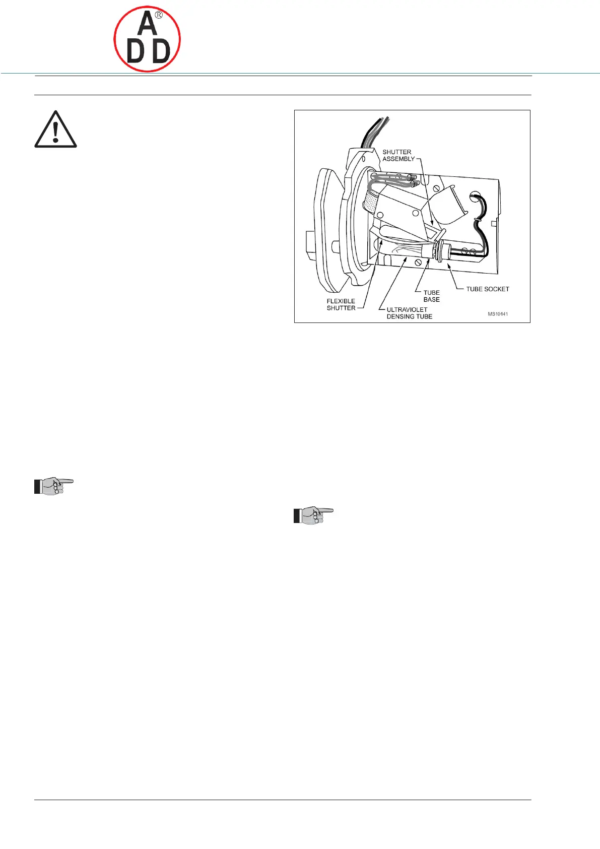
Fig. 12. Replacing ultraviolet radiation sensing tube.
Replacing the Coil and Shutter Assembly
NOTE: Use only a 190971 B coil and shutter assembly.
A
Open the master switch and remove the detector cover
(see Removing the Detector Cover section).
B
Remove the ultraviolet sensing tube (steps A through E
of Replacing the Ultraviolet Sensing Tube section).
Replacing the Ultraviolet Sensing Tube
A
Open the master switch and remove the cover from the
detector (see instructions above).
B
Locate the UV sensing tube.
IMPORTANT
Be very careful not to kink or otherwise damage
the flexible shutter.
C
Gently bend the alignment guide just enough to free the
tip
D
of the tube.
Insert a screwdriver between the tube base and socket,
E
and gently pry the tube out of its socket.
F
Pull the tube out of its socket.
Insert the new tube through the openings in the shutter
G
assembly.
Align the three pins on the new tube with the holes in the
H
socket.
Carefully push the new tube firmly into its socket; the
alignment guide will snap into place around the tip of the
I
tube.
J
Make sure the new UV sensor tube is seated securely.
C
Cut the white wires as close as possible to the crimped
connectors and remove the crimped connectors.
D
Remove the three mounting screws from the base of
the coil and shutter assembly. Put the screws in a safe
place.
E
Remove the coil and shutter assembly.
F
Put the new coil and shutter assembly into place.
IMPORTANT
Be very careful not to kink or otherwise damage
the flexible shutter.
G Insert the three mounting screws into the base of the coil
and shutter assembly and tighten securely.
H
Remove sufficient insulation from each of the two white
lead wires remaining on the detector, and from each of
the two white lead wires on the new coil.
I
Using solderless connectors, connect one of the coil
wires to one of the remaining white lead wires.
Connect the other coil wire to the other remaining white
J lead wire. Reinstall the sensing tube (steps F through I
of Replacing the Ultraviolet Sensing Tube section).
K Replace the detector cover.
 Loading...