บริษัท เอดีดี เฟอร์เนส จํากัด
ADD FURNACE CO.,LTD.
44 ซอยบรมราชชนนี 70 ถนนบรมราชชนนี แขวงศาลาธรรมสพน์ เขตทวีวัฒนา กรุงเทพฯ 10170
โทร: 02-888-3472 โทร: ออกแบบ:08-08-170-170 แฟกซ์: 02-888-3258
https://www.add-furnace.com E-mail: sales@add-furnace.com
VARIOUS
TROUBLESHOOTING
CAUTION
1.
Be extremely careful while troubleshooting
the detector: line voltage is present on some
of the terminals when power is on.
2.
Open the master switch to disconnect power
before removing or installing the detector or
its cover. More than one disconnects may be
involved.
Equipment Required
A volt-Ohm meter with a minimum sensitivity of one megohm
/ Volt and a zero to fi e or ten Vdc scale is suggested. When
the keyboard display module is available, a flame signal
displays on the module. For revision of a flame safeguard
control using the R7061 amplifier, use the W136 or a similar
test meter. For replacement parts, see specifications section
UV Sensor Tube Test
see UV sensor tube test section.
Unsatisfactory Flame Signal
If a satisfactory flame signal (see Table 1) cannot be
obtained while adjusting the sighting position of the
detector, follow these procedures. If you encounter other
problems in the system, refer to the Troubleshooting
section in the instructions for the appropriate flame
safeguard control. NOTE: For instructions for replacing
the viewing window, sensing tube, and coil and shutter
assembly, see the service section.
Troubleshooting Procedures
First perform the preliminary inspection. Then follow the
applicable procedures for either a low reading or a zero
reading on the meter. After reinstalling the detector or
replacing its cover, recheck the meter reading. To try to
obtain the proper flame signal, adjust the position of the
detector. If you complete all of the procedures and still
cannot obtain a proper flame signal, replace the detector.
Preliminary Inspection
A
Check for the proper line voltage. Make sure the master
switch is closed, connections are correct, and power
supply is of the correct voltage and frequency.
B
Check the detector wiring for defects:
a.
Incorrect connections.
b.
Wrong type or size of wire.
c.
Deteriorated wire.
d.
Open circuits.
e.
Short circuits.
f.
Leakage paths caused by moisture, soot, or dirt.
C
With the burner running, check the temperature at the
detector. If it exceeds 79°C (175°F):
a.
Add additional insulation between the wall of the
combustion chamber and the detector.
b.
Add a shield or screen to reflect radiated heat away
from the detector, or
c.
Add cooling (refer to sight pipe ventilation and
accessories sections).
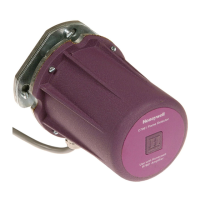
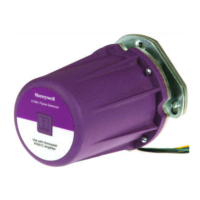
Removing the Detector from the Sight Pipe
C7061A:
Loosen the three screws holding the mounting flange
together; rotate the detector slightly so the screws clear the
slots in the back section of the flange; separate the flange;
and pull off the back section (with the UV Sensor).
NOTE: The detector will be free as soon as the collar is
unscrewed; do not drop it.
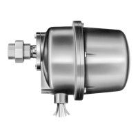
C7061F:
Carefully unscrew from sight pipe
Procedure for a Zero Meter Reading
A
Replace the plug-in amplifier. Then recheck the flame
signal.
B
Replace the ultraviolet sensing tube (see Service
section). Then recheck the flame signal
C
Replace the coil and shutter assembly (see Service
below). Then recheck the flame signal
D
If you still cannot obtain a meter reading, replace the
detector.
IMPORTANT
At the completion of troubleshooting, be sure to
perform the adjustments and checkout
procedures.

 Loading...