- Observe proper polarity.
- If not using the integrated EOL resistors, set all switches to
OFF.
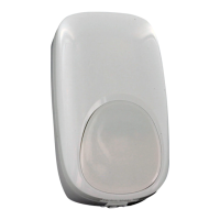
- If using the integrated EOL resistors:
1. Connect the sensor to the panel (see wiring diagrams
below).
2. Set the appropriate tamper [RT], alarm [RA] and trouble [RF]
DIP switches to ON (see Step 4 on page 2).
Notes:
- Consult the Control Panel manual to determine
proper EOL selection.
- The Alarm, Tamper and Trouble EOL settings must
each only have one switch ON.
- The EOL values should be set at the same time.
Wiring Examples
Alarm, Tamper and
Trouble configured
to one loop.
Alarm, Tamper and
Trouble configured
to two loops.
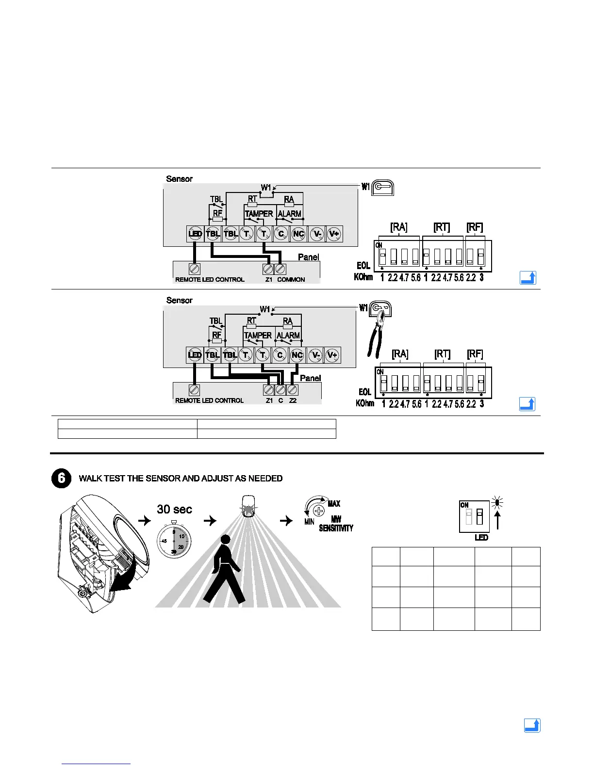
1. Close the sensor and apply power to the sensor. Initialization is
complete when the LED stops flashing slowly (about 30 seconds).
2. Walk through the detection area and observe the LED.
3. Adjust the microwave range as necessary to meet installation requirements.
Walk test mode is active for 10 minutes, then automatically exits test mode,
disables the LED and enters normal operation mode. For an additional 10
minute walk test, enable walk test mode again with the flashlight feature (see the
following page).
RF = Trouble EOL resistor
W1 = 1 and 2 loop connection resistor.
- During power up and walk test
modes the LED is active
regardless of the LED
Enable/Disable DIP switch setting.
- When the microwave sensitivity is
set to minimum, the sensor range
is reduced to 5m.
LED Power Up
Microwave
OFF OFF
Green OFF
ON
PIR
OFF OFF
 Loading...