Extinguishing Control Computer 8010 - Series 2
FB 798352 / 11.07 87
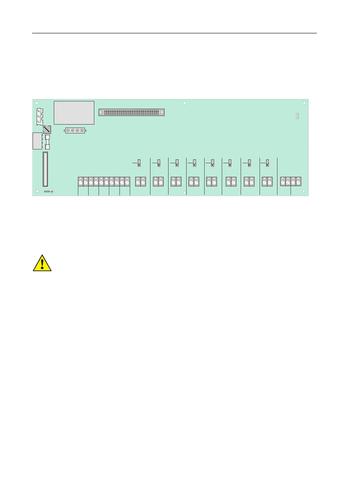
17.2 Zone board
The zone board allows eight alarm zones to be connected for automatic fire detectors series 9000 and/or 9100
as well as manual call points (MCP).
The alarm zone operating mode (standard or EDD) is set via the associated plug-in jumpers (J1 to J8). Mixed
operation on one alarm zone of series 9000 and 9100 automatic fire detectors is not permissible.
N
PE
L1
F1
T4A
X1
X2
X3
+ - + - + - + - + -
F2
T1A
X16
J9
X4
X5
power voltage
Trafo secund.
MAN.
ALARM
EM.
STOP
FAILURE
EXTING.
System 1
groung fault
identification
TRAFO PRIMÄR
+ -
detector zone 8
Std.
EDD
+ -
detector zone 7
Std.
EDD
+ -
detector zone 6
Std.
EDD
+ -
detector zone 5
Std.
EDD
+ -
detector zone 4
Std.
EDD
+ -
detector zone 3
Std.
EDD
+ -
detector zone 2
Std.
EDD
+ -
detector zone 1
Std.
EDD
EXTRA
RELEASE
Zone card
connection prozessor card
BLOCKING
to power supply- and relay card
DZ 14
+ -
BUZZER
OFF
DZ 15
+ -
RESET
Fig. 24: Zone board / position of the subassemblies
Five technical zones are available for non-automatic detectors (manual call points, push-button controls) and
inputs for connecting trouble contacts.
When connecting the mains voltage and the protective earth, refer to the instructions in the
chapter “Mains connection and earthing“.
 Loading...