Extinguishing Control Computer 8010 - Series 2
98 FB 798352 / 11.07
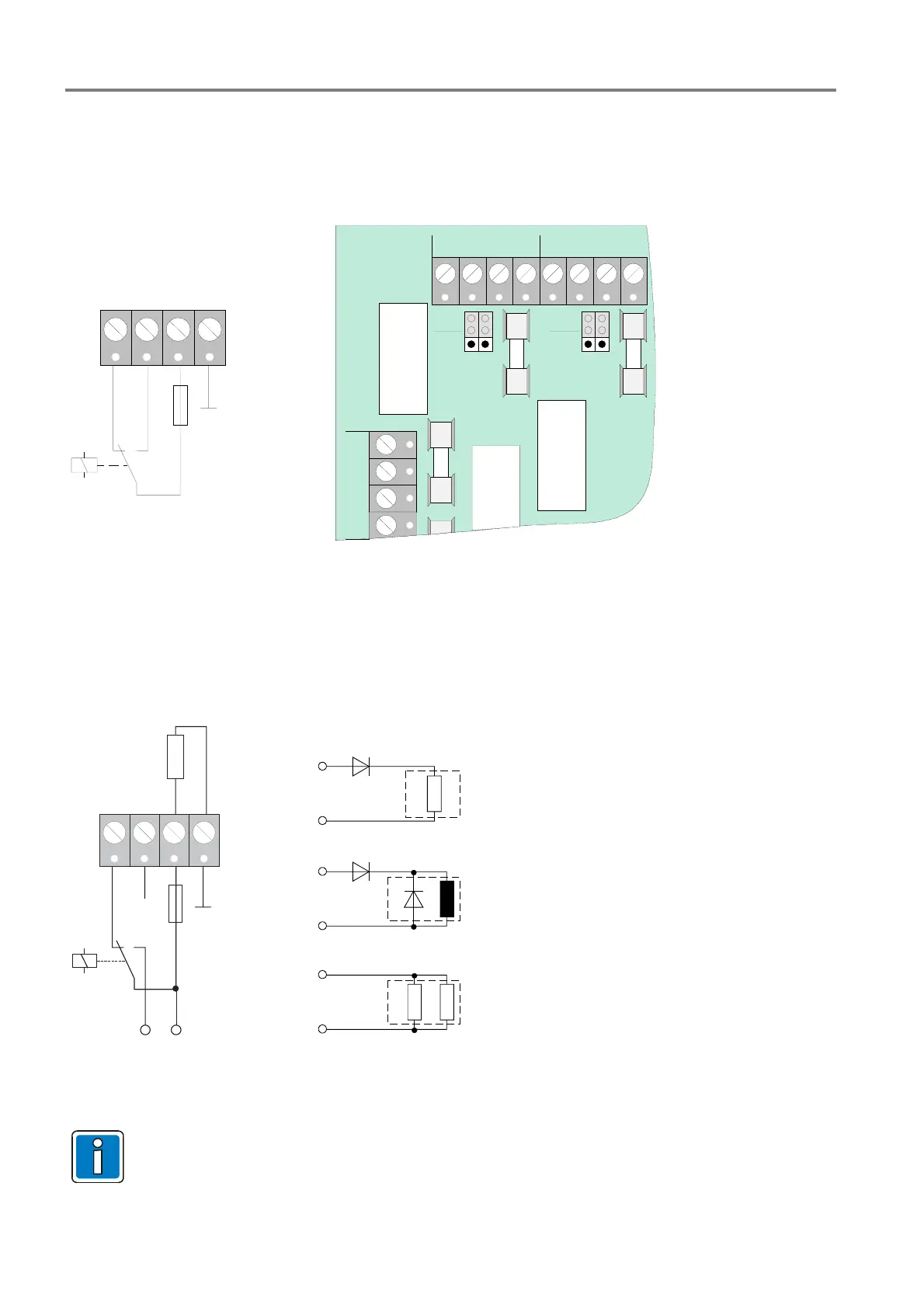
17.3.2 Operating mode of the relays no. 1 to 8
Dry contact
The two operating modes >dry contact< or >monitored< can be selected for the relay outputs No. 1 to No. 8 with
the corresponding jumpers.
T2A
NC
NO
C
GND
pot.-
free
moni-
tored
NC NO C NC NO C
REL 8 REL 7
NC NO C
REL9
F5
F6
F2
pot.-
free
moni-
tored
Fig. 31: Dry contact (Schematic wiring)
Positive-switching and monitored (relays 1 to 8)
The cable to the external device is monitored with this operating mode. For this purpose, a current of 1 mA with
the same polarity as the control voltage is fed in with the relay in the de-energized position. If anything happens,
the relay is activated and the voltage (24 V DC) is switched to the external unit. In the resting state, a voltage of
approximately 1 V DC to 2 V DC must be present at the relay terminals during the monitored mode. This
requires an external connection, depending on the application:
N C
N O
C
G N D
T 2 A
R *
2 4 V D C
m o n i t o r i n g
( t e s t c u r r e n t )
R
L
= low-resistance load R < 300 Ohm
D
1
= series diode BY251 (notice relays current max. 2 A)
L = inductive load
D
1
= series diode BY251 (notice relays current max. 2 A)
D
2
= recovery diode e.g. 1N4007 o.ä.
R
L
= high-resistance load > 2 kOhm
R = parallel resistor 2 kOhm
R
L
D
1
L
D
1
D
2
R
L
R
relay
+
-
+
-
+
-
relay
relay
Fig. 32: Positive-switching / monitoring mode (Schematic wiring)
Only silicon diodes type BY251 must be used for this application!
 Loading...