Extinguishing Control Computer 8010 - Series 2
FB 798352 / 11.07 63
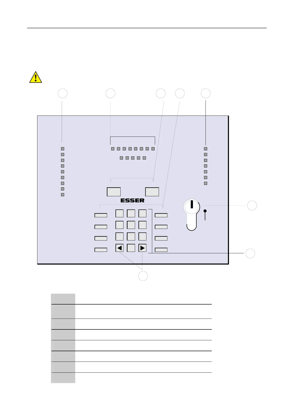
12 Display and control panel
It is possible to integrate the optional display and control panel (Part No. 788401) in the housing door. All
operations of the Extinguishing Control Computer can be carried out with the clearly arranged function keys.
The keys can be locked with the built-in key switch.
For a single stand-alone system a control panel is always required.
Un-
locked
12 34
6
5
8
Disconnection
In operation
Switching off
Test operation
Extra releasing 1
Outputs
Alarm
Switchover
Buzzer off
Lamp test
Zone
Output
Panel reset
On
Off
Test operation
1
4
7
0
8
5
2 3
6
9
Common trouble
Emergency
operation
Power trouble
Battery trouble
Ground fault
Trouble 1
Blocking
7
Emergency release
Detector zone
Fire/Switch off/Trouble
12345678
9 10111213
K
e
y
b
o
a
r
d
R
e
l
e
a
s
e
Extinguishing system
activated
Extinguishing system
enabled
Fig. 1: Display and control panel
c
Operating displays
d
Detector zone display (no.1 to no.8)
Technical zones (no.9 to no.13)
e
Function keys (freely accessible)
f
Function keys (behind the keypad cover)
g
trouble indicators
h
Key-switch
i
Ten-button keypad (behind the keypad cover)
j
Arrow keys (behind the keypad cover)
 Loading...


