40
FireLite SLC Wiring Manual — P/N 51309:R3 7/29/2019
Monitor Modules MMF-302 Wiring Diagrams
5.6 MMF-302 Wiring Diagrams
Following are wiring diagrams that concern NFPA Class B and Class A Initiating Device Circuits (IDCs) using MMF-302 Zone Inter-
face Modules.
5.6.1 Wiring a NFPA Class B IDC with an MMF-302
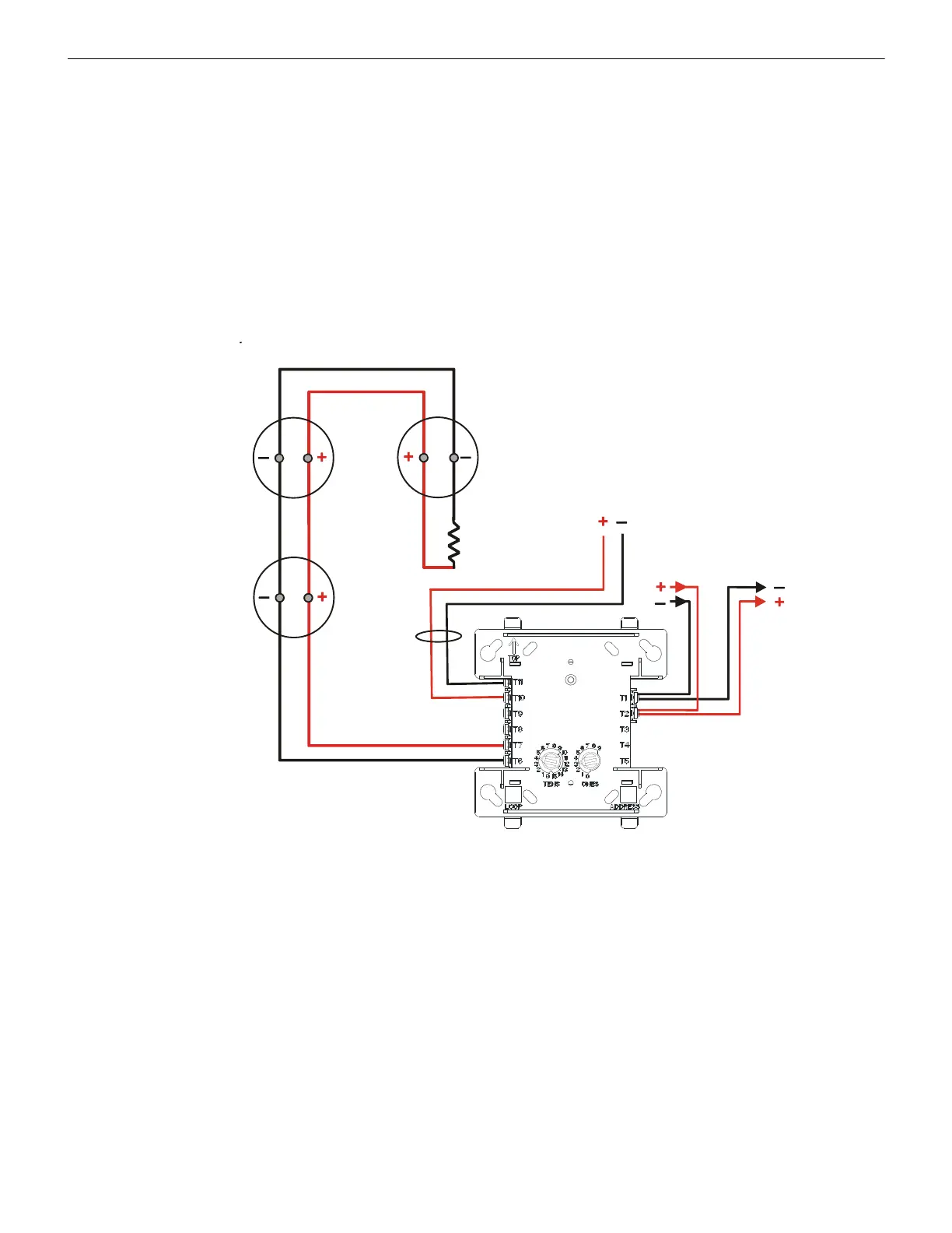
Connect the SLC wiring to the module terminals 1 (–) and 2 (+).
Each module takes one address on the SLC. Use the rotary switches on the module to set it to the required SLC address. Refer to “Setting
an SLC address for a Single Point Module” on page 33.
The IDC is supervised and power limited to 230 microamperes @ 24 VDC.
The figure below shows typical wiring for a supervised and power-limited NFPA Class B IDC using an MMF-302 module.
• Refer to the Device Compatibility Document for compatible smoke detectors.
• 24 VDC power must be provided from a UL listed power supply for fire protection use. This power is inherently supervised by th
e
module.
• See “Power Considerations” on page 63 for information on 24 VDC power.
SLC
IDC
SLC-idcB2tpH.wmf
MMF-302
Two-wire
smoke
detectors
3.9K ELR
(supplied with module)
24 VDC Resettable power.
90 mA External 24 volt
supply required
Figure 5.15 Typical Class B IDC Wiring with an MMF-302

 Loading...


