22
FireLite SLC Wiring Manual — P/N 51309:R3 7/29/2019
Section 4: SLC Circuits with Isolators
4.1 Fault Isolator Devices
There are three isolator devices used to protect critical elements of the SLC from faults on other SLC branches or segments.
• Fault Isolator Module I300
• Six Fault Isolator Module ISO-6
• Isolator Detector Base B224BI
A Fault Isolator Module on both sides of a device, or the combination of Isolator Base and Isolator Module is required to comply with
NFPA Class X requirements.
4.1.1 Isolating an SLC Branch
The module continuously monitors the circuit connected to terminals 3(–) and 4(+). Upon power-up, an integral relay is latched on. The
module periodically pulses the coil of this relay. A short circuit on the SLC resets the relay. The module detects the short and disconnects
the faulted SLC branch or segment by opening the positive side of the SLC (terminal 4). This isolates the faulty branch from the remain-
der of the loop preventing a communication problem with all other addressable devices on the remaining branches (labeled “Continua-
tion of the SLC” in the figure below). During a fault condition, the control panel registers a trouble condition for each addressable device
which is isolated on the SLC segment or branch. Once the fault is removed, the module automatically reapplies power to the SLC branch
or segment.
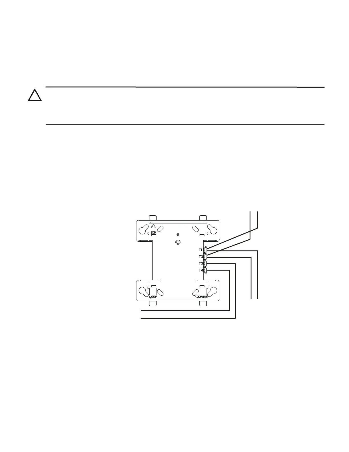
4.1.2 Wiring an Isolator Module
The figure below shows typical wiring of an I300 Isolator Module:
CAUTION: MAXIMUM ADDRESSABLE DEVICES
• If relay or sounder bases are not used, a maximum of 25 addressable devices can be connected between Isolator Modules and/or
Bases. When relay or sounder bases are used, the maximum number of addressable devices that can be connected between Isolators
is reduced to seven. Isolator modules will not function properly when these limits are exceeded.
• When more than 100 Isolator Modules are connected to an SLC loop, the address capacity of the loop is reduced by two (2) addresses
for every isolator device in excess of 100.
SLC
Isolated branch
of the SLC
SLC-isowire2.wmf
Continuation
of the SLC
OUT
OUT
IN
IN
Figure 4.1 Wiring an I300 Module

 Loading...


