Wire detectors to zones Galaxy Flex Installer Manual
16
2. Connect an RS485 data cable between the panel and each device in a daisy-chain
configuration, using the information in the tables below.
Note: Do not use spur and star configurations.
We strongly recommend you use a twisted-pair screened cable (Belden 8723
equivalent, Cat 5/5e). However, for cable runs of less than 100 m in normal
environments, standard 4-core cable can be used.
Panel
Keypad/
Keyprox
TouchCenter
RIO/DCM
PSU
Audio
Interface
Telecom
Ethernet
RF
Portal
+12 V
+ + Vin X* +12 V +12 V + +
GND – – – 0 V GND - - -
A A G A A A A A A
B B Y B B B B B B
* Do not connect power supplies in parallel. Do not connect +12 V terminals between
the control panel and remote power supplies. However, connect the 0 V (negatives)
of all power supplies at a common reference point.
Wire detectors to zones
Note: Learning wireless detectors is covered on page 20.
Zones are the individual input circuits that are fully programmable using the Zones menu
(52 ent). This section describes how to change zone default settings, how to terminate
unused zones, and how to connect detectors.
Zone addressing
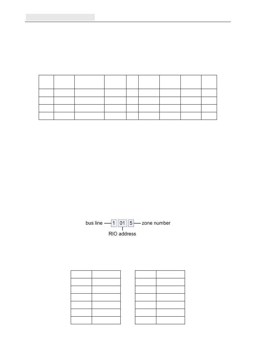
The zone address format is:
The RIO address range is 00 to 12, and each RIO can handle up to 8 zones.
Note: 00 and 01 are the fixed onboard RIO addresses.
Address onboard zones as follows:
Zone Address Zone Address
1 1001 7 1013
2 1002 8 1014
3 1003 9 1015
4 1004 10 1016
5 1011 11 1017
6 1012 12 1018
If required, use the Descriptor menu (52 ent 2 ent) to name your zones.

 Loading...


