HPF-PS Series Instruction Manual — P/N LS10227-003HP-E:C 2/2/2022 21
Ground Fault Detection Installation
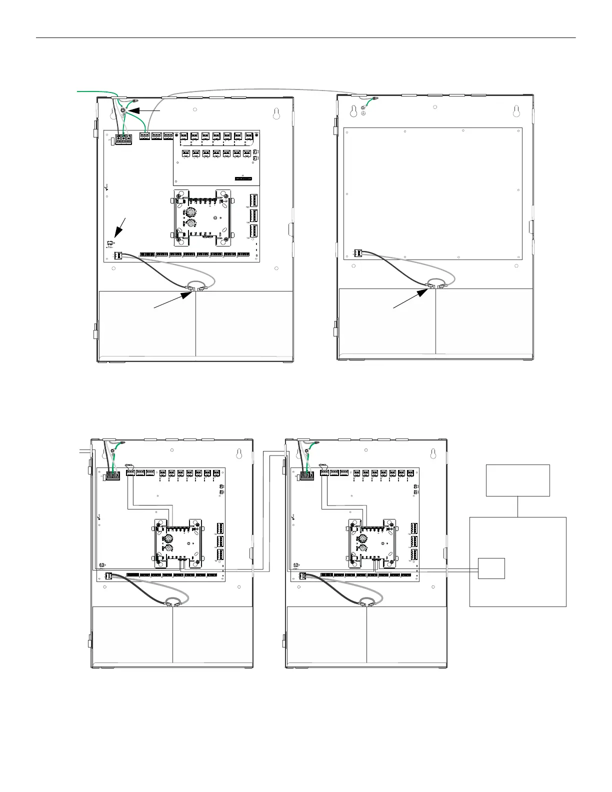
battery terminals, including FACP battery terminal. Ground faults must then be detected by the first HPF-PS in the chain. Disable
ground fault detection on other HPF-PS units by sliding SW1 to the left. Ensure ground fault detection is enabled on HPF-PS1, the first
power supply from the FACP, by sliding SW1 to the right. 18 AWG wire minimum must be used.
2. Ground fault monitoring may be accomplished by mapping an annunciator point on a UL 864-listed FACP as ground fault. The
annunciator shall be wired adjacent to the FACP so all displays are grouped for viewing and operation by one person.
Addressable FACP: The FACP must be programmed to turn on the common trouble LED, trouble tone, and a separate yellow
annunciator point when the monitor module connected to the HPF-PS ground fault relay is initiated. The annunciator point must also be
labeled as “XXX Ground Fault” where “XXX” describes ground fault origin.
NO NC CNONC C
TB4
TB15
NO NC C
T
B
3
T
B
2
T
B
1
T
B
1
3
T
B
1
2
T
B
1
1
T
B
1
0
T
B
9
T
B
8
NAC1
AUX1
NAC2
AUX2
A- B+ B- A+ A- B+ B- A+ A- B+ B- A+
Host FACP Power Supply
optional
ZNAC-PS
converter
card
SW1 ground fault
detection switch
wire nut, ground
cables, and
ground stud
Figure 2.14 Ground Fault Detection Option 1
Battery -
Battery -
to next
negative
battery
terminal
NO NC CNONC C
TB4
TB15
NO NC C
T
B
3
T
B
2
T
B
1
T
B
1
3
T
B
1
2
T
B
1
1
T
B
1
0
T
B
9
T
B
8
NAC1
AUX1
NAC2
AUX2
NO NC CNONC C
TB4
TB15
NO NC C
T
B
3
T
B
2
T
B
1
T
B
1
3
T
B
1
2
T
B
1
1
T
B
1
0
T
B
9
T
B
8
2
A- B+ B- A+
A- B+ B- A+A- B+ B- A+
A- B+ B- A+
A- B+ B- A+A- B+ B- A+
UL 864-listed
addressable control
panel
UL 864-listed
annunciator
SLC
-
+
Figure 2.15 Ground Fault Detection Option 2 - Addressable FACP
Maintain 0.25” spacing
between power-limited and
non-power-limited wiring.
to next
monitor
module

 Loading...


