HPF-PS Series Instruction Manual — P/N LS10227-003HP-E:C 2/2/2022 35
General Trouble Relay Trouble Supervision
5.2 General Trouble Relay
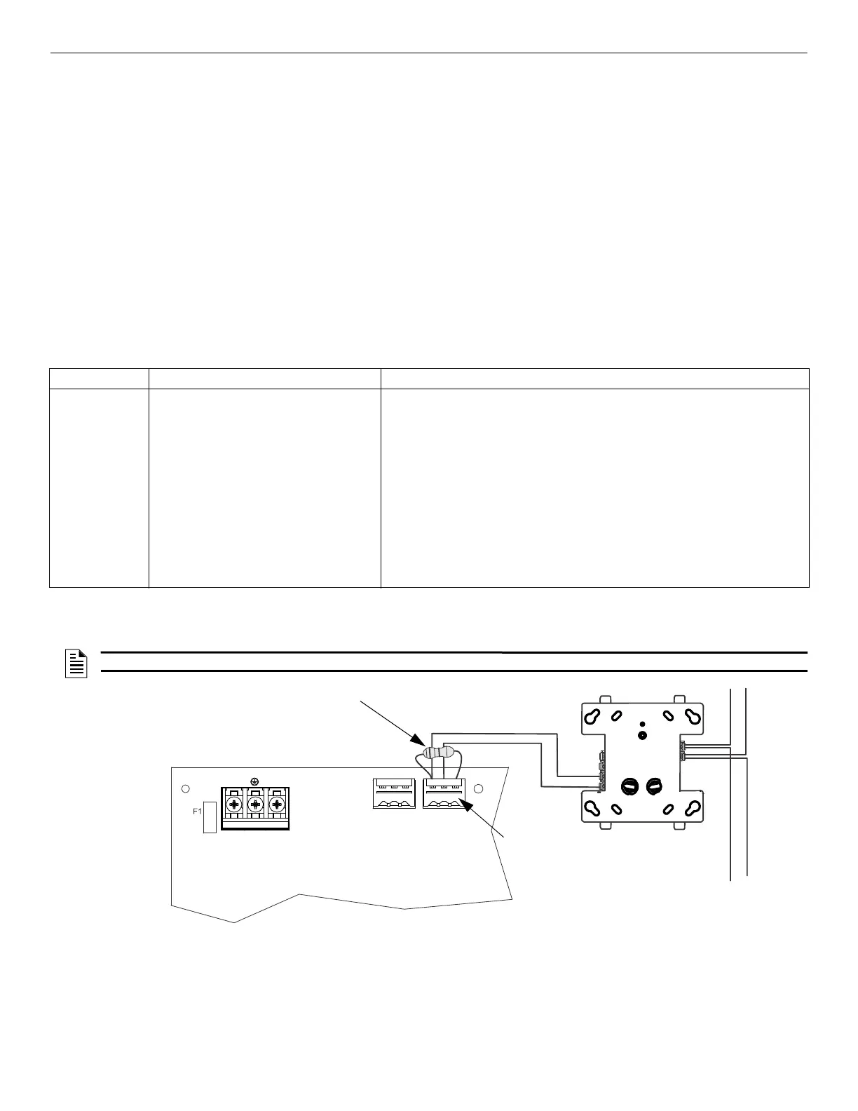
The HPF-PS power supply has a fail-safe Form-C trouble relay located at TB1. The contacts can be monitored by an FACP input circuit or
an addressable monitor module as illustrated in Figure 5.1. Note that any faults reported by Command Inputs are not repeated by the trouble
relay in Default Mode, offering limited trouble reporting. For Retrofit Mode trouble reporting, refer to Table 5.1 above and Table 5.2 below.
When the power supply is configured for Retrofit Mode, the FACP should be monitoring either Input #1/Input #2 end-of-line relay or the
General Trouble Relay, but not both.
Trouble conditions that will cause the normally energized trouble relay to change states regardless of whether the panel is in alarm or standby:
• A battery fail condition at the power supply
• A battery charger fail on the power supply
• A ground fault condition on the power supply (in Retrofit Mode if S1 Global DIP switch 8 = OFF)
• An AC fail condition (only in Retrofit Mode, if S1 Global DIP switch 8 = OFF)
• A field wiring fault on the HPF-PS outputs configured as resettable aux power, non-resettable aux power, or door holder aux power
• A total panel overload fault
• A blown AC fuse
• A field wiring fault on the NAC output configured as Slave, Master, or Master Selective Silence Outputs (only in Retrofit Mode)
The following table summarizes the trouble supervision using the General trouble relay in both Default Mode and Retrofit Mode.
Note that when the power supply is configured in Retrofit Mode, the FACP should be monitoring either Input #1/Input #2 end-of-line relay
or the Internal trouble relay, but not both.
If trouble monitoring is required when the power supply is in alarm, the General Trouble Relay at TB1 can be used for this purpose. Refer to
Figure 5.1 below.
Panel Status Default Mode Retrofit Mode
General Trouble
relay in Standby
and Alarm
• Any new or existing battery, charger, panel
overload, AC fuse, or ground trouble
conditions are reported.
• Any new or existing fault conditions of
resettable aux power, non-resettable aux
power, or door holder outputs are reported.
• Any new or existing battery, charger, panel overload, or AC fuse trouble conditions
are reported.
• Any new or existing fault conditions of resettable aux power, non-resettable aux
power, or door holder outputs are reported.
• Any new open, short, ZNAC faults, or power-limiting conditions of Slave or Master
(non-selective silence) NAC outputs which are mapped to command Input 1, Input
2, Input 3, or mapped to ALL inputs are reported.
• Any new open, short, ZNAC faults, or existing power-limiting conditions of Master
selective silence NAC outputs are reported.
If S1 Global DIP switch 8= OFF
• Any new or existing AC trouble or ground fault trouble are reported (with 0 or 2h
AC trouble delay depending on S1 Global DIP switch 7 Configuration).
If S1 Global DIP switch 8=ON
• Any new or existing ground fault trouble will be reported.
Table 5.2 Operating Mode Behavior for the General Trouble Relay
NOTE: The individual NAC Trouble LED will indicate which NAC circuit is in trouble.
NO NC C NO NC C
TB4
T
B
2
T
B
1
T1
SLC
Monitor Module*
Monitor Module ELR
HPF-PS
T7
T6
NO
NC
*If the SLC device does not
match the one in this figure, refer
to the SLC manual wiring con-
version charts for legacy and
newer versions of the modules.
AC
Trouble
Trouble
Trouble Relay
Figure 5.1 Monitoring the Trouble Relay

 Loading...


