HPF-PS Series Instruction Manual — P/N LS10227-003HP-E:C 2/2/2022 27
Output Circuit Control DIP Switch Settings Programming Options
Display Trouble History Mode
To see past troubles on the system, place position 9 to OFF and position 10 to ON. Refer to Section 4 for descriptions of troubles. Trouble
history will be erased upon exiting the Display Trouble History operating mode.
The behavior of the Display Trouble History Mode with regard to the Sync Input Configuration and Trouble reporting will depend on which
was the last active (minimum 5 minutes) operating mode, Default or Retrofit, before entering Display Trouble History Mode.
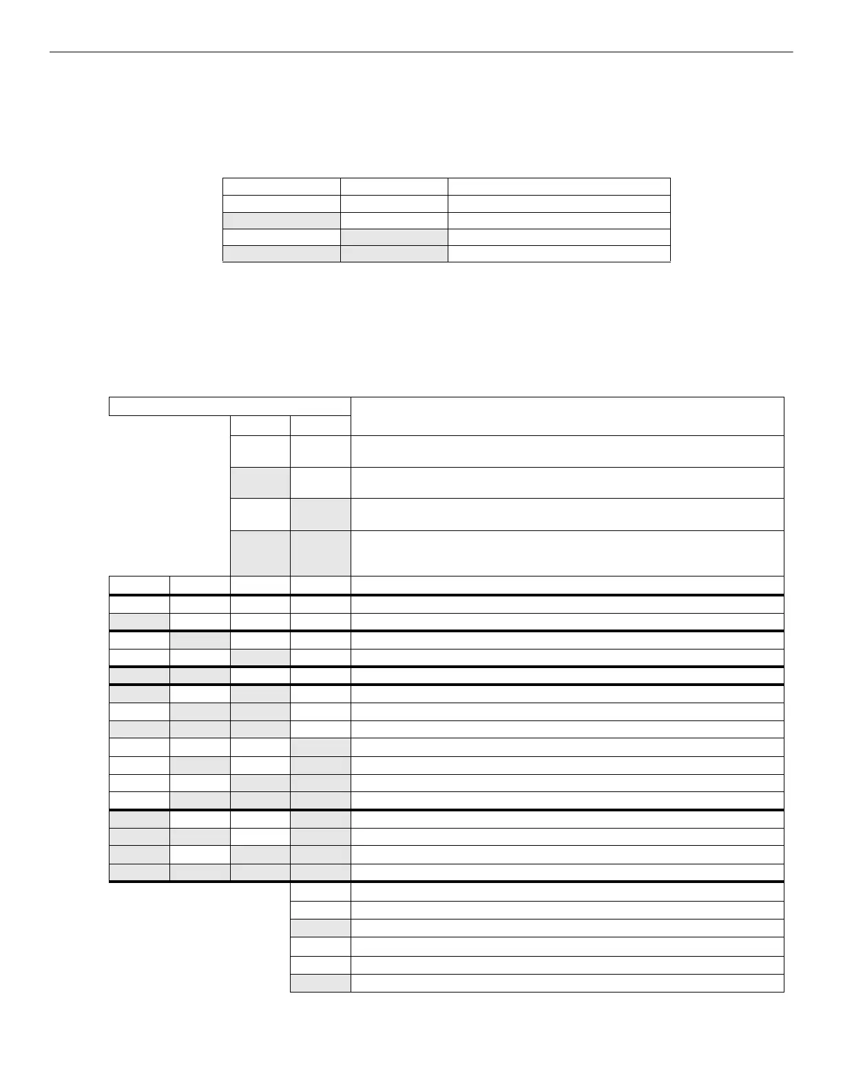
DIP switch positions 9 and 10 are used to select the type of operating mode as listed below:
3.2 Output Circuit Control DIP Switch Settings
Each output circuit has its own programming DIP switch. DIP switches S2-S8 are labeled on the PCB to indicate which output circuit it is
controlling. Output circuits are labeled at the top of the PCB, TB8-TB14.The following table applies to DIP Switches S2-S8.
Important! If an output circuit is overloaded, the output will shut off and generate a trouble signal. If this happens, the HPF-PS will need to
be reset manually. Either reset circuit configurations by toggling switch S1 position 10 to the OFF position for a minimum of five seconds or
turn off primary and secondary power and reapply to the HPF-PS.
Position 9 Position 10 Operating Mode
OFF OFF Retrofit Mode
ON OFF Change output circuit configurations
OFF
ON Display Trouble History
ON ON Default Mode
Table 3.8 Operating Mode
DIP Switch Position
Output Control Setting/Operation
12
OFF OFF NAC output will activate when Command Input #1 is activated.
Do not use this setting when Input#1 is set to Sync Configuration.
ON OFF NAC output will activate when Command Input #2 is activated.
(Exception: this Input controls Horn silencing during Selective Silence operation.)
OFF
ON NAC output will activate when Command Input #3 is activated, if available. (If
accidentally programmed on a HPF-PS6, the system will default to Input #2.)
ON ON NAC output will activate when ANY Command Input is activated.
If Input #1 is set to Sync Configuration (Global DIP switch 3 = OFF), this setting applies
to Input#2 and Input#3 only.
3 4 5 6 Output Control Setting/Operation
OFF OFF OFF OFF Unused/Unsupervised. Outputs will not activate. Factory default setting.
ON OFF OFF OFF Reserved- Outputs will not activate
OFF
ON OFF OFF Non-resettable auxiliary power
OFF OFF
ON OFF Resettable aux power
ON ON OFF OFF Door holder auxiliary power
ON OFF ON OFF Slave Configuration (NAC follower)
OFF
ON ON OFF Master Configuration - ANSI Temporal (Temporal 3)
ON ON ON OFF Master Configuration - CO Temporal (Temporal 4)
OFF OFF OFF
ON Master Configuration - Amseco/Potter
OFF
ON OFF ON Master Configuration - Gentex
OFF OFF
ON ON Master Configuration - System Sensor
OFF
ON ON ON Master Configuration - Wheelock
ON OFF OFF ON Master Configuration, Selective Silence - Amseco/Potter
ON ON OFF ON Master Configuration, Selective Silence - Gentex
ON OFF ON ON Master Configuration, Selective Silence - System Sensor
ON ON ON ON Master Configuration, Selective Silence - Wheelock
7 Output Control Setting/Operation (Only applies when ZNAC-PS is installed)
OFF Class B
ON Class A
8 Output Control Setting/Operation (Unused)
OFF Unused/Unassigned
ON Unused/Unassigned
Table 3.9 S2-S8 Output Circuit DIP Switch Settings

 Loading...


