Application Examples Controlling NACs, Aux Power, and Door Holders with NAC Sync
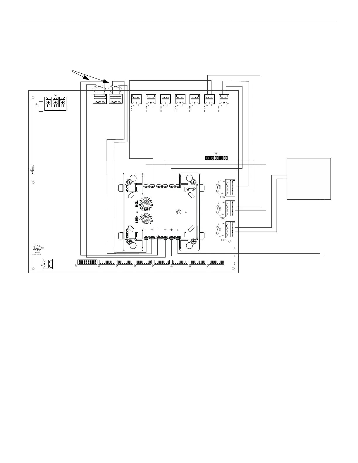
B.4 Controlling NACs, Aux Power, and Door Holders with NAC Sync
In this application, use of a single TC822A1010 mounted inside the cabinet can monitor the two power supply trouble relays and trigger two
independent inputs via relay circuits. HPF-PS outputs #1 and #2 are being used for 24 VDC aux power triggered by the module’s relay cir-
cuits. Any HPF-PS output circuit can be configured to follow any input circuit.
The following notes apply to Figure B.4.
• Any output circuit can be configured as NAC, door holder, or 24VDC power.
• Refer to Section 3 for instructions on setting the DIP switches.
• Do not loop wires under screw terminals. Break wires to maintain proper supervision.
• An End-of-Line Resistor must be installed between terminals 1 and 4 for module wiring supervision (the ELR value is dependent on the
module/FACP employed).
• An End-of-line Resistor on input circuits#1-2 (TB5-6) are optional for this particular application.
• Ensure that the TC822A1010 is programmed appropriately at the FACP where the inputs are not mapped to the same zone as its
outputs.
• For a list of compatible devices, refer to the HPP Device Compatibility Document #54399.
• Refer to the SLC Wiring Manual for more information.
NO NC CNONC C
TB4
TB15
T
B
2
T
B
1
T
B
1
3
T
B
1
2
T
B
1
1
T
B
1
0
T
B
9
T
B
8
T1
T2
T3
T4
T5
T6
T12 NC
T11 C
T10 NO
T9 NC
T8 C
T7 NO
A-
NAC or Remote
Sync Output
FACP
SLC
TC822A101
Figure B.4 Controlling NACs, Aux Power, and Door Holders with One Input and NAC Sync
End-of-Line Resistors
supplied with Module
24VDC Aux Power
AC
Trouble
Trouble
46
HPF-PS Series Instruction Manual — P/N LS10227-003HP-E:C 2/2/2022

 Loading...


