Application Examples Controlling NACs For Sync Follower Operation Using a Control Module (Default Mode Configuration Only)
B.2 Controlling NACs For Sync Follower Operation Using a Control Module (Default
Mode Configuration Only)
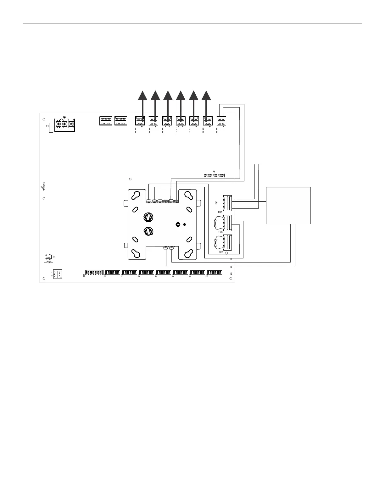
In this application, the power supply has been set to operate in Slave Configuration and will follow the sync signal from the FACP. This
application requires Input #1 to be controlled by the FACP sync output. Input #1 may be wired to the next HPF-PS or terminate in and ELR.
Input #2 (or Input #3, if available) will act as the trigger signal for the output circuits. The control module can be powered by one of the HPF-
PS output circuits, configured as aux power (24VDC). See Table 3.14 on page 29 for DIP switch settings.
The following notes apply to Figure B.2.
• When the HPF-PS power supply is in an inactive state (control module not active), a trouble on the NAC circuits mapped to TB6 will
result in an open circuit condition on the control module output circuit (monitored by End-of-Line Resistor across TB6, Terminals 1 and
4). As an alternative, the trouble contacts at TB1 of the power supply can also be used for limited trouble monitoring excluding faults
reported by Command Input #2 related to Command Input#1 configured for Sync Input Configuration. Refer to Section 5 for more
information.
• Refer to Section 3 for instructions on setting the DIP switches.
• Output faults are reported via Command Input#2 with Command Input#1 configured for Sync Input Configuration operation.
• Refer to the FACP manual for load restrictions and line length limitations when wiring multiple power supplies at the input.
• Wire NACs as shown on page 14.
• Do not loop wires under screw terminals. Break wires to maintain proper supervision.
• An End-of-Line Resistor must be installed across all input circuits, Terminals 1 and 4, for control module wiring supervision (the ELR
value is dependent on the module/FACP employed).
• For a list of compatible devices, refer to the HPP Device Compatibility Document #54399.
• Refer to the SLC Wiring Manual for more information.
NO NC CNONC C
TB4
TB15
T
B
2
T
B
1
T
B
1
3
T
B
1
2
T
B
1
1
T
B
1
0
T
B
9
T
B
8
T1
T11
T2
T10
T3
T9
T4
T8
T5
T7
T6
A- B+ B- A+ A- B+ B- A+ A- B+ B- A+
Figure B.2 Controlling Multiple Outputs with One Input as Sync Follower
Control Module*
SLC
*If the SLC device does not match
the one in this figure, refer to the
SLC manual wiring conversion
charts for legacy and newer ver-
sions of the modules.
NAC Output Circuits
24VDC power output
NAC Sync
FACP
to next PS Series
Power Supply or ELR
44
HPF-PS Series Instruction Manual — P/N LS10227-003HP-E:C 2/2/2022

 Loading...


