9-3
To maintain sensor accuracy when using the
pyrolyzer, perform a gas calibration every six
months. Do not allow the ambient temperature at
the point of installation to exceed 40°C (104°F).
Operation above this temperature may require
more frequent bump testing or calibration to
confirm working specification. Because of the
higher operating temperatures when using the
pyrolyzer module, Honeywell Analytics strongly
recommends that the ventilated Midas Top
Cover (part number MIDAS-A-039) be used in all
pyrolyzer applications.
NOTE: The Pyrolyzer module is serviceable only
by trained personnel or by Honeywell Analytics’
Service Center. Inappropriate handling can cause
injury and device damage.
Note: Le module pyrolyzer pouvant-être réparé.
Par contre la réparation doit-être effectuée par
un personnel qualifié ou à un centre de service
autorisé d’Honeywell Analytics. Une manutention
inadéquate pourrait causé des blessures ainsi que
des dommages à l’appareil.
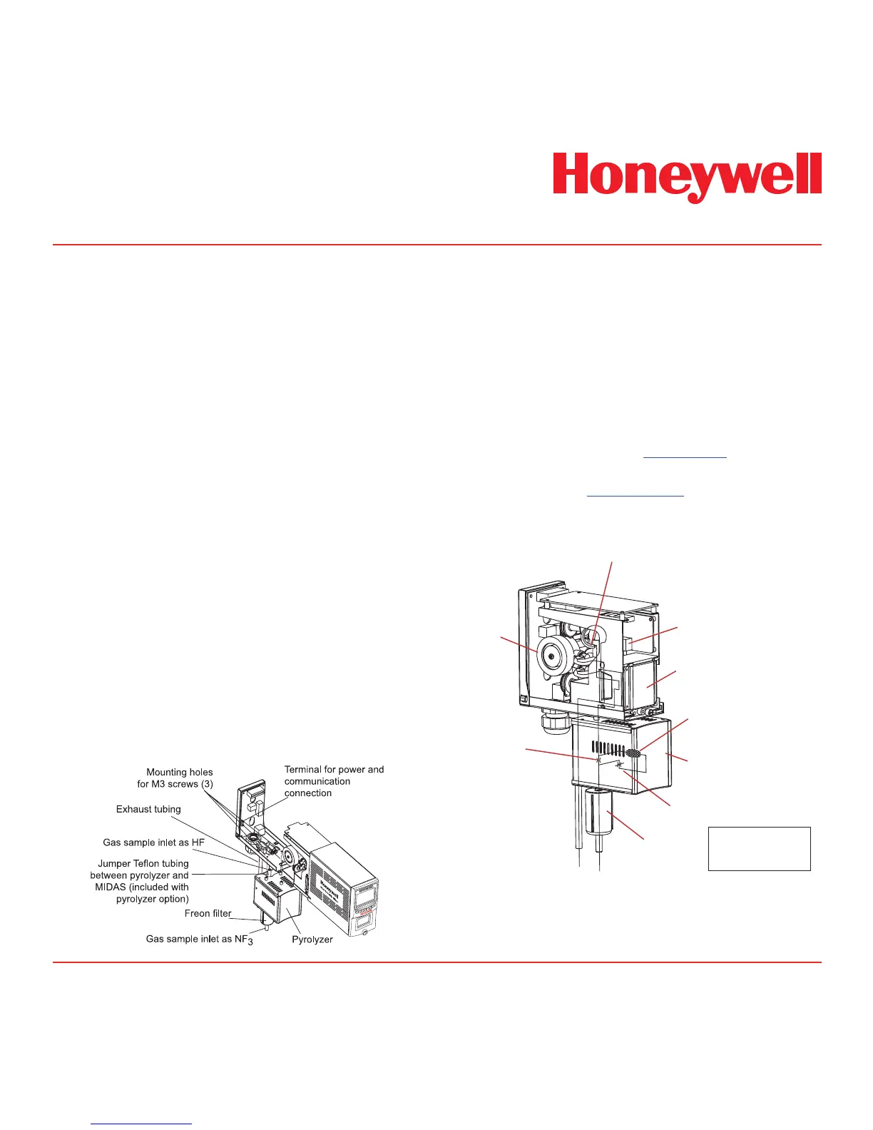
Diagram 9-2 shows the main components of the
pyrolyzer.
Diagram 9-2. Pyrolyzer components.
Diagram 9-2. Pyrolyzer components.
Diagram 9-3 shows in a simple form how a gas
sample is drawn through the pyrolyzer module by
the pump (located at the end of the gas path). It
is first routed to the pyrolyzer via the Freon filter
before being sent to the gas sensor cartridge,
where the gas measurement is taken. The sample
continues via the flow meter through the dust
filter and is finally exhausted from the instrument.
Adjustment of the gas flow through the instrument
is done automatically. It is recommended to
perform a leak check (see Section 8.5) before
performing a flow calibration. To perform a flow
calibration refer to Section 7.3.3.
Diagram 9-3. Pyrolyzer conguration gas ow.
Pyrolyzer Heater
Pyrolyzer
Gas sample
Inlet
Gas sample
Exhaust
Pump
Freon
filter
Pressure sensor
Orifice
(Bypass flow)
Gas sensor
 Loading...