10-6
value is twice the fault number. For example when
a flow failure (Fault F81) exists, the raw value of
nvoFaultS will be {0xA2, 0x01}. This is displayed by
LonMark-compatible tools as {81.0, 1}.
Alarm Thresholds
The variables nvoAlmThres1 and nvoAlmThres2
reports the configuration of the alarm setpoints. The
scaling and format of the data is identical to that
used with nvoConc. These are read-only data – it
is not possible to change the alarm settings over
LonWorks
®
.
nvoGasSelection
This NVO facilitates determining over the network
what cartridge is installed and which calibration
is selected. The most-significant byte of this is
equal to the sensor cartridge ID number. The least-
significant byte of this is equal to the gas ID number.
Values for both are listed in Appendix B.
nvoCellLife
This reports the time remaining until the F43
(“Cartridge Expired”) is issued. Fault m12 (“Cartridge
Expires Soon”) will generally be issued 30 days
before F43. However, this variable provides no
advance warning of fault m11 (“User Cal Expired”).
nvoMonState
The bits in this variable are shown graphically
in Table 10-2. The least-significant 4 bits form
a monitoring mode integer (MMI). Bit 7-2 form
a heartbeat counter which increments every 2
seconds. The heartbeat counter is provided to
facilitate confirmation of communication. This
variable propagates every nciMinSendT since it is
always changing.
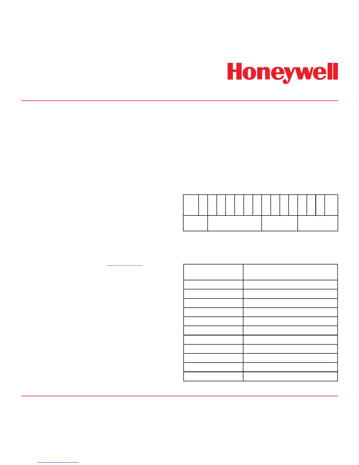
Table 10-2. nvoMonState Bit Assignment
bit
0
MSB
bit
1
bit
2
bit
3
bit
4
bit
5
bit
6
bit
7
bit
8
bit
9
bit
10
bit
11
bit
12
bit
13
bit
14
bit
15
LSB
Always
Zero
Heartbeat
Counter
Always Zero
Monitoring Mode
Integer
The description of the Monitoring Mode Integers are
listed in Table 10-3 below.
Table 10-3. Monitor Mode Integer Description
Monitoring Mode
Integer
Description
0 Warmup
1 Monitoring without inhibit
2 Alarms inhibited
3 Alarms, and faults inhibited
4 Alarms, faults and concentrations inhibited
5 Simulation
6 Bump test mode
7 4-20 mA calibration mode
8 Other calibration mode
9 to 14 for future expansion
15 Communications failure.

 Loading...