AMPS-24 Manual — P/N 51907:J2 02/26/2014 13
LED Indicators Introduction
There are eighteen LEDs that indicate various conditions and troubles. The following table lists and
describes each.
Reference LED Name Color Description
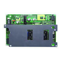
AMPS-K2
Board
2 STATUS Green
•
+5V logic power and software indication
• Normally slow blink (1 blink/sec)
• Off in self-test failure or SLC address = 0 (bootloader)
• Steady on memory Flashing and POR (+5V check)
3 RESET Yellow
RESET active.
4 GEN TBL Yellow
•
Slow blink (1 blink/sec) if SLC address = 0 (bootloader)
• Blinks once then pause in CPS communication failure
• Fast blink (5 blinks/sec) in self-test failure or programming
• Steady in any other trouble, POR and memory Flashing
5 TBL BUS Yellow
Steady when external trouble bus signal received (trouble bus shorted)
6 SLCRX Green
SLC incoming data
7 SLCTX Green SLC outgoing data
8 485TX Green
485 outgoing data
9 485RX Green
485 incoming data
10 MAIN 24V Green
+24V at Main output
11 MAIN 24V TBL Yellow
•
Steady if in current-limit
• Fast blink (5 blinks/sec) in hardware failure
• Steady on memory Flashing, or RAM self-test failure
• Medium blink (3 blinks/sec) on application code CRC self-test failure
12 AUX 24V TBL Yellow
•
Steady if in current-limit
• Fast blink (5 blinks/sec) in hardware failure
• Steady on memory Flashing, PCB rev test failed
• Medium blink (3 blinks/sec) on application code CRC self-test failure
13 AUX 24V Green +24V at AUX output
CPS-24
Board
1 LOGIC POWER Green
+5V logic power
2 TROUBLE Yellow
Coded trouble indicator: 1 blink = AC failure; 2 blinks - high battery; 3
blinks = low battery; 4 blinks = charger failure
3 EARTH FAULT Yellow Ground fault detected
4 AC Green
AC is on
5 +24V AUX Green
+24V Auxiliary power
6 +5V AUX Green
+5V Auxiliary power
Table 1.3 LED Indicators

 Loading...