20 AMPS-24 Manual — P/N 51907:J2 02/26/2014
Installation Wiring the AMPS-24/E
2.7 Wiring the AMPS-24/E
2.7.1 Overview
Complete all mounting procedures and check all wiring before applying power. Electrical
connections are listed below and are detailed in the following paragraphs:
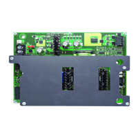
AMPS-K2 (rear board)
TB1 - MAIN 24V
Main output, 5 A, 24VDC (nominal), output.
•5A
1) with 5A charger and AUX 24V output disabled, or
2) with 1A charger and 3A AUX 24V, or
3) with 2A charger and 3A AUX 24V,
OR
• 3A (with 5A charger and 1A AUX 24V)
These values are described in table format in Table 1.1 on page 8.
TB3 - AUX 24V
Auxiliary 24V output provides filtered power-limited (Class 2) power for additional components.
• 5A (charger disabled)
• 3A (1A/2A charger)
• 1A (5A charger and 3A Main 24V output)
These values are described in table format in Table 1.1 on page 8.
TB2 - SLC Wiring
Connect to panel Signaling Line Circuit. This terminal is not used when the AMPS-24 is connected
to a panel or DS-DB via the EIA-485 connection.
TB4 - TBL BUS
Trouble bus input is designed to receive trouble signals from any normally open dry contacts or
open collector circuit.
J3 - USB
USB Type B connector for Power Supply configuration using a PC.
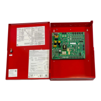
CPS-24 (front board)
TB1 - AC
Primary AC Power Source - 120 VAC, 50/60 Hz, 5A (AMPS-24E uses 220-240 VAC, 50/60 Hz,
2.5 A) from line voltage source.
WARNING: Risk of electrical shock!
Remove all power sources to equipment while connecting electrical components. Leave the external,
main power breaker OFF until installation of the entire system is complete.
WARNING: Risk of equipment damage!
Several sources of power can be connected to the control panel and/or power supply. Before servicing
the control panel, disconnect all sources of input power including the battery. While energized, the control
panel and associated equipment can be damaged by removing and/or inserting cards, modules, or
interconnecting cables.

 Loading...