NFS2-3030 Listing Document — P/N LS10006-051NF-E:F2 5/19/2022 17
Installing a Security Tamper Switch
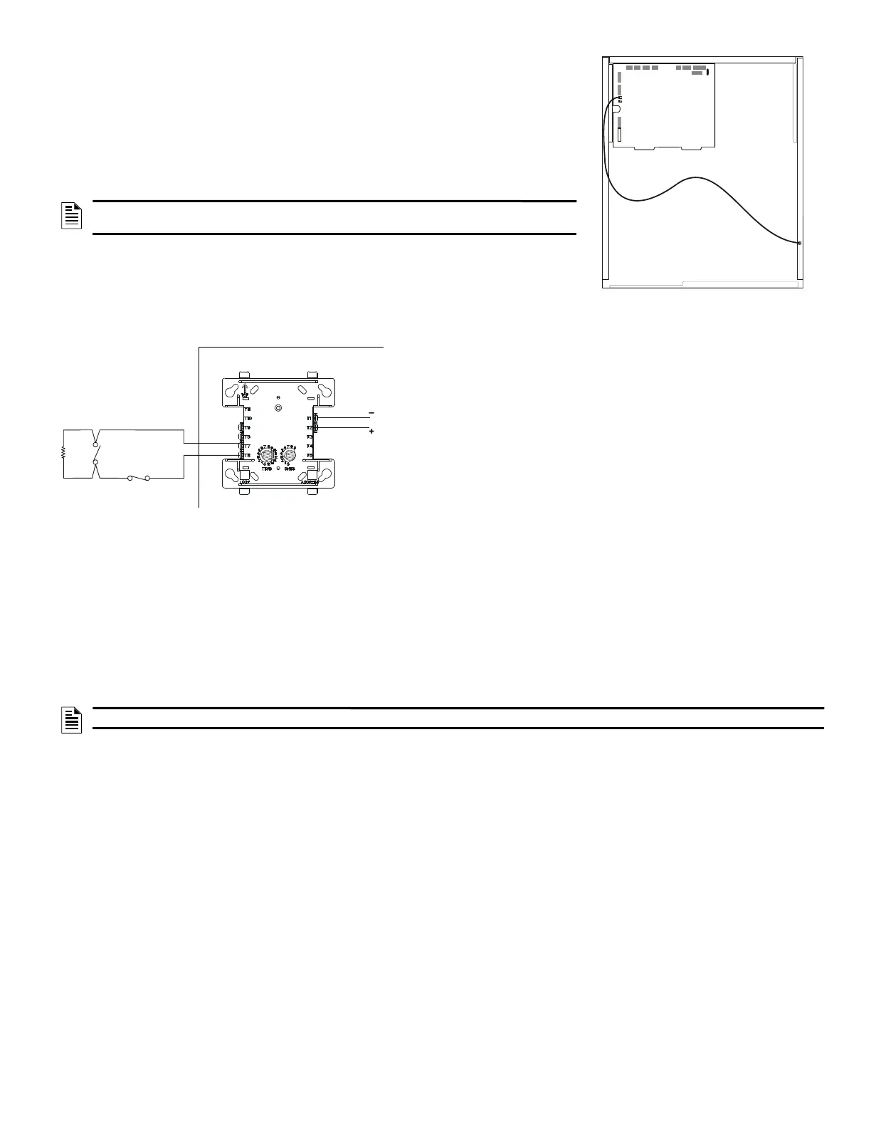
Follow the instructions below to wire the cabinet with a Security Tamper Switch kit model STS-1:
1. Install the STS-1 Tamper Switch onto the side of the backbox opposite the door hinge, pushing the
switch through the opening until it snaps into place.
2. Install the magnet on the same side of the cabinet door as the lock. Push the magnet through the
opening in the door until it snaps into place.
3. Connect the STS-1 connector to J6 Security on the CPU.
4. Program panel supervision for Tamper Input “Yes”.
Programming
The control panel can communicate with any number of security devices. To do so, select the address of
the module to be used for security and assign one of the type codes described in General Security
Requirements on page 16.
Proprietary Security
Alarm Applications
For security applications, program one or more monitor modules (listed for
security applications) with a security type code.
Note the following:
•The module is programed as an ACCESS MONIITOR, AREA MONITOR,
EQUIP MONITOR, SECURITY-L, or SYS MONITOR type code.
•Supplementary use applies to UL Systems only.
•NAC devices used for security cannot be shared with fire NAC devices.
•Refer to the Device Compatibility Document, document number 15378, for
compatible NAC devices.
•All monitor modules used for security applications must be installed in the
control panel with an STS-1 Security Tamper Switch.
Wiring for Proprietary Security Alarm Applications
Typical wiring for proprietary security alarm applications with the FMM-1 module.
Note the following:
• The module is programmed with one of five type codes (see “General Security Requirements” on page 16).
• Supplementary use only applies to UL-listed systems.
• NAC devices used for security cannot be shared with fire NAC devices.
• Refer to the Device Compatibility Document for compatible NAC devices.
All monitor modules used for security application must be installed in the control panel cabinet with STS-1 Security Tamper Switch.
Connecting an RKS-S Remote Key Switch
The RKS-S Remote Key Switch arms and disarms the system. It can be mounted in a UL listed single-gang electrical box. Both the monitor module
and RKS-S must be mounted within the protected area. Refer to the Product Installation Document (15984) for information on how to wire the RKS-S
to a FMM-1 and FMM-101 module.
Single Tenant Security System with Entry/Exit Delay
The following system requirements are illustrated in Figure 19 on page 18.
• One NFS2-3030 Control Panel
• Multiple Security Supervisory Circuits Reporting to Central Station as a Single Area
• The minimum security equipment required is as follows:
– Multiple MM Monitor Modules per Protected Area
– One Group Interface for security alarm
– One Group Interface to generate trouble arming system
– Contact Switch for Each Entry/Exit Door
– RKS-S Key Switch
– MM Monitor Modules
– Remote Annunciator for Each Entry/Exit Door (ACM-24AT, ACM-48A, ACM-16AT, ACM-32A)
– Security Devices
– RM Relay Module
NOTE: Total SLC points connected to the FACP are limited to 1000 or less for
security applications
NOTE: If NAC devices are used, the audible pattern for a Security Alarm signal should be distinct from a Fire Alarm
STS-1
mounting
location
(side opposite
Connect to
J6 Security
Figure 17 Installing the STS-1
Security Tamper Switch
47K
End-of-line
UL-listed,
normally-open
NFS2-3030 Protected Premises Unit
UL-listed,
normally-closed
FMM-1
SLC
Channel A
or B
Figure 18 Wiring Diagram for Proprietary Security Alarm

 Loading...


