N200-102-00 8 I56-3947-202
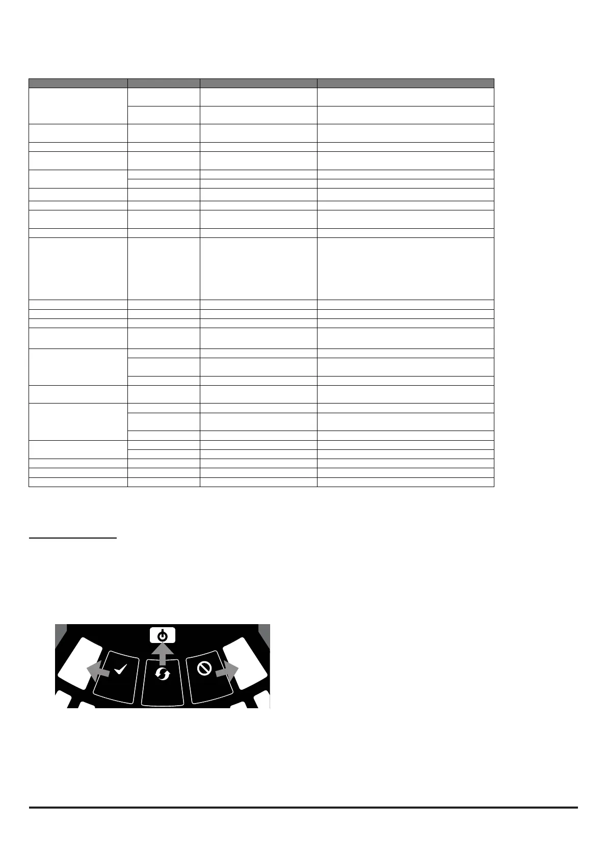
Table 4: Front Panel Indicators and Fault Descriptions
S
ENSO
R
A
S
P
I
RA
T
O
R
D
R
I
F
T
C
O
M
P
E
N
S
A
T
I
O
N
TEMPERATURE / INPUT
DISABLE / SYSTEM
S
OU
N
D
E
R
F
I
L
T
E
R
LO
W
FLO
W
HI
G
H
FLO
W
INITIALIZATION
LEVEL 1
SMOKE
FAULT
FAULT
POWER
LEVEL 2
SMOKE
INITIALIZATION
ALARM
PREALARM
2
10
3
1
4
5
6
7
8
9
2
10
3
1
4
5
6
7
8
9
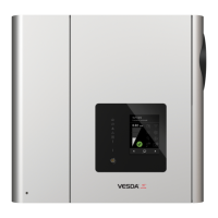
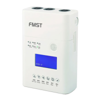
Figure 12: User Interface Buttons
Note: The channel alarm and smoke level LEDs are under the
control of the CIE (Fire Panel).
Front Panel Buttons
The front panel has 3 user buttons: TEST, RESET and DISABLE.
These buttons are used to enter the pass-code which then allows
the user to carry out simple test functions.
Note: In Remote Maintenance and Service Mode, these buttons
are always disabled.
INDICATOR ACTION WARNING OR TROUBLE COMMENT / ACTION
CHANNEL 1/2 ALARM ON Red
(Set by panel)
Channel is in alarm (relay is
set ON with no delay)
Default setting
1 BLINK Green
(Polled by panel)
When sensor is polled Not when in alarm
CHANNEL 1/2 PRE-
ALARM
ON Yellow Channel is in pre-alarm Only with panels using Advanced Protocol
SMOKE LEVEL 1/2 ON Yellow
(Set by panel)
Led number indicates sensor
alarm level reached
Only numbers 1 – 9 used - only with panels
using Advanced Protocol
CHANNEL 1/2 MODULE ON Green Controlled by panel
BLINK Green Module communication Controlled by panel
FAULT ON Yellow Common or multiple faults
POWER ON Green FAAST LT is powered Displays Yellow when initialising
POWER FAULT ON Yellow Low power alert / high power
fault
Check the power supply voltage.
CHANNEL FLOW
INDICATORS 1/2
ON Green The LED indicates the air flow
for a channel:
- Centre = normal flow
- Left = flow low;
(-20% at extreme)
- Right = flow high;
(+20% at extreme)
On 2 channel unit:
Upper row = Ch1
Lower row = Ch2
LOW FLOW ON Yellow Low flow fault Check filter; check pipe network for blockages.
INPUT 1 BLINK Yellow External input fault Not used with default settings
SENSOR 2 BLINKS Yellow Sensor communication fault Check sensor addresses and installation;
replace sensor.
ASPIRATOR ON Yellow Air flow sensor fault Try to restart device.
1 BLINK Yellow Flow initialization fault Check filter; check pipe network for blockages;
try to restart device.
2 BLINKS Yellow Fan fault Try to restart device.
DISABLE 1 BLINK Yellow Alarms & alerts not reported Returns to Maintenance then Normal operation
after 60min (default)
SYSTEM 1 BLINK Yellow Wrong configuration Flashes all FAULT LEDs; try to restart device.
2 BLINKS Yellow EEPROM fault Check power supply voltage. Try to restart
device
3 BLINKS Yellow Real time clock fault RTC is corrupted or time reading failed.
TEMPERATURE 1 BLINK Yellow Low temperature alert Check the air flow temperature
2 BLINKS Yellow High temperature alert Check the air flow temperature
SOUNDER 1 BLINK Yellow Sounder fault Check the sounder circuit and the EOL
FILTER 1 BLINK Yellow Filter alert at set date No date set as default
HIGH FLOW ON Yellow High flow fault Check pipe network for breaks or leaks.
In case of simultaneous alerts/faults on the same LED, priority order is: ON (Highest), 1 blink, 2 blinks, 3 blinks (Lowest)

 Loading...