N200-102-00 9 I56-3947-202
Password Sequence to Enter Maintenance Mode
Press and hold RESET; Left ow indicator will turn yellow, then
green.
Release RESET and FAULT indicator will switch on green. The
left ow indicator will blink green indicating the device is ready for
the rst digit.
Press DISABLE to increment the LEDs 1…9; press TEST to select
a digit.
The ashing airow segment will turn solid green and the next
segment will begin to ash indicating set the next digit. When the
4th digit is selected, all 4 airow segments are turned off. If the
password is accepted the FAULT indicator will remain green and
the unit enters Maintenance mode. If the password is incorrect
the FAULT indicator ashes yellow and the unit remains in Normal
mode. The Default password in 3111.
If no button is pressed for 10s during the password sequence, the
unit returns to Normal mode.
Exit from Maintenance Mode
To exit from the Maintenance mode, press the three front panel
user interface buttons TEST, RESET and DISABLE simultaneously
for 2 seconds. Alternatively, reset the unit using the Remote Input
(when set to default value) or power the device off and on again.
If there is no activity in Maintenance mode for 5 minutes (default),
the FAULT indicator blinks green for 15s and then the unit
automatically returns to the Normal state.
TESTING
Note that the sensor LEDs, which are under the control of the CIE
(Fire Panel), must be turned on to activate the front panel alarm
indicators.
Magnet Test
The alarm signalling can be tested for functionality by placing a
test magnet in the position shown in Figure 9 (displayed earlier in
the guide). This method does not test the air ow in the pipe-work.
Smoke Testing
The system alarm response can be tested for functionality
using smoke. The choice of smoke source is dependant on the
installation but in all cases the smoke must be present for the
duration of the test. Smoke pellets or matches can be used close
to the sampling point to introduce smoke particulates into the
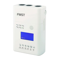
Table 5: Front Panel Buttons
system. It is recommended that smoke with a particulate life cycle
of greater than 120s should be used – standard aerosol sprays for
point detector testing do not work well on aspirated systems.
Fault Testing
Simulate a fault on the detector (for example, block the outlet pipe)
and check that a fault is signalled on both the front panel of the unit
and at the CIE (Fire Panel).
SERVICE
WARNING
Isolate the aspirating detector from the re alarm system to prevent
any unwanted alarms when opening the front door of the unit.
Make sure all power is removed from the system before removing
any covers.
Service Mode
Opening the cabinet door during normal operation will cause the
unit to enter Service Mode. The FILTER LEDs will blink, the unit will
switch off power to the fans and stops communicating with the re
panel (the smoke sensors continue to communicate with the panel).
When the cabinet door is closed, the unit restarts automatically.
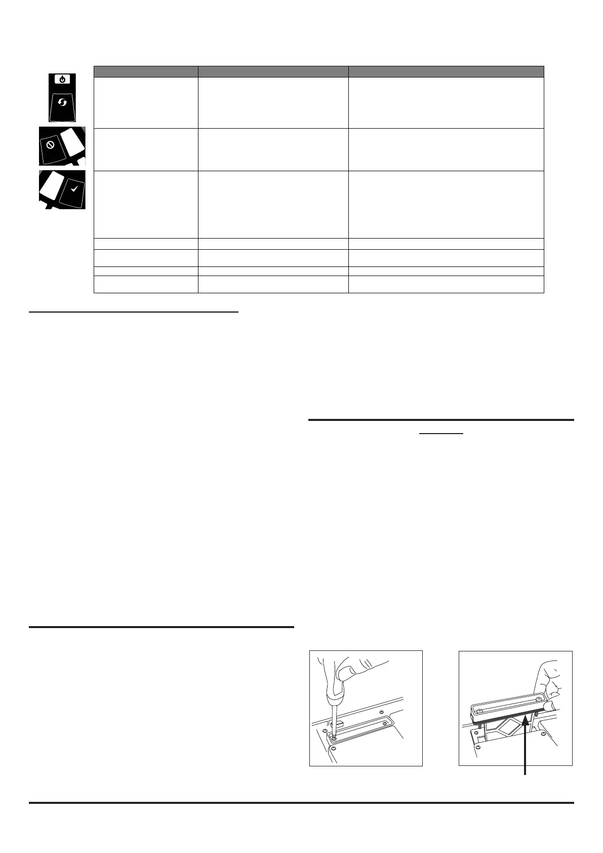
Filters
Periodic cleaning or replacement of the lters will be required.
The lters are located inside the cabinet at the top of the unit (see
Figure 9 displayed earlier in the guide) and are removed as shown
in the sequence below:
S
E
N
S
O
R
A
S
P
I
RA
TOR
D
R
I
F
T
C
OM
P
E
N
S
A
T
I
O
N
TEMPERATURE / INPUT
DISABLE / SYSTEM
S
O
U
N
DE
R
F
I
L
T
E
R
L
O
W
F
L
O
W
H
I
G
H
F
L
O
W
INITIALIZATION
LEVEL 1
SMOKE
FAULT
FAULT
POWER
LEVEL 2
SMOKE
INITIALIZATION
ALARM
PREALARM
2
10
3
1
4
5
6
7
8
9
2
10
3
1
4
5
6
7
8
9
S
E
N
SO
R
A
S
P
I
R
A
T
O
R
D
R
I
F
T
C
O
M
P
E
N
S
A
T
I
O
N
TEMPERATURE / INPUT
DISABLE / SYSTEM
S
O
U
N
D
E
R
F
I
L
T
E
R
L
O
W F
L
O
W
H
I
G
H
F
L
O
W
INITIALIZATION
LEVEL 1
SMOKE
FAULT
FAULT
POWER
LEVEL 2
SMOKE
INITIALIZATION
ALARM
PREALARM
2
10
3
1
4
5
6
7
8
9
2
10
3
1
4
5
6
7
8
9
S
E
N
S
O
R
A
S
P
I
R
A
T
O
R
D
R
I
F
T
C
O
M
P
E
N
S
A
T
I
O
N
TEMPERATURE / INPUT
DISABLE / SYSTEM
S
O
U
N
D
E
R
F
IL
T
E
R
L
O
W
F
L
O
W
H
I
G
H
F
L
O
W
INITIALIZATION
LEVEL 1
SMOKE
FAULT
FAULT
POWER
LEVEL 2
SMOKE
INITIALIZATION
ALARM
PREALARM
2
10
3
1
4
5
6
7
8
9
2
10
3
1
4
5
6
7
8
9
F i lters
Either replace the filter assembly or carefully brush off the accumulated dust.
Refit the filter, close and secure the cabinet door. The unit will initialise and restart.
1 2
BUTTON NORMAL Mode MAINTENANCE Mode
RESET When pressed for 2 s, starts PASSWORD
PROCEDURE to enter Maintenance
mode.
When pressed for 2 s latched alarms, faults and
sounders (relays) are reset. Alarm controlled by panel. If
alarm persists, set again immediately after the reset
In DISABLE Mode, if pressed for 2 s unit will exit from
DISABLE Mode (but remains in MAINTENANCE Mode)
DISABLE Used to increment Password digits in
PASSWORD PROCEDURE
When pressed for 2 s, device enters DISABLE Mode for
60 minutes (default). Alarm and fault relays reset .
Smoke sensors continue to report alarm and their faults
to the panel.
(To exit DISABLE Mode see RESET)
TEST Used to confirm password in PASSWORD
PROCEDURE. Default Password = 3111
When pressed for 2 s and released, both sensor will
simulate alarm
When pressed for 4 s and released, sensor #1 will
simulate alarm
When pressed for 6 s and released, sensor #2 will
simulate alarm
Warning: Outputs will be activated by test
COMBINATIONS
RESET + DISABLE When pressed for 2 s, shows fan speed
(on smoke level scales) for a preset time.
When pressed for 2 s, shows fan speed (on smoke level
scales) for preset time.
RESET + TEST No action When pressed for 2 s, turns off sounders
RESET + TEST + DISABLE No action When pressed for 2 s, unit exits from MAINTENANCE
Mode
FOAM GASKET

 Loading...