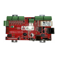
Commissioning information S4 Mains powered interface unit
2 4188-968 issue 2_Part 2_09-10_S4 mains interface
How to install batteries and Power up
The following illustration shows how to connect a pair of 12V 12Ah batteries for S4-34440-12 or 12V 2.1Ah
batteries for S4-34440-02 into a S4 Mains powered interface unit. The numbers j, k, l.. shows the order in
which to carry out the installation.
&
DO NOT fit the 12V 2.1Ah batteries inside the S4-34440-12 Mains powered interface unit .
Status Indicator LD1
Indicator LD1 colour meaning...
FLASH Green OK - Interface replies to a loop communication sequence.
Long FLASH
with loop communications
Amber There is a short circuit, open circuit or confirmation timeout on an
interface zone / sector channel.
Short FLASH Amber The interface loses synchronisation with the loop communications
sequence.
ON
continuously
Amber System error is detected (e.g. a configuration memory checksum /
validity check error or a Flash / RAM error).
A
A
P7
2 x 12V 2.1Ah Batteries
2 x 12V 12Ah Batteries
A
Mains Powered Interface PCB
a
ns
owere
Interface PCB
2 x 12V 2.1Ah Batteries
Black
Red
Mains Powered Interface
Status
indicator
ON
FLASH
LD1
Link
Battery
lead
Battery
lead
Link
P7
Mains Powered Interface PCB
2 x 12V 12Ah Batteries
Red
Black
Link
Battery
lead
Link
Battery
lead
The status indicator will only come
on if the unit has mains power or if
the batteries are connected and the
"battery power up" push is operated.
www.acornfiresecurity.com
www.acornfiresecurity.com

 Loading...


