Sensepoint XCD RFD Technical Manual SPXCDHMRFEN Issue 4_08-2016
25
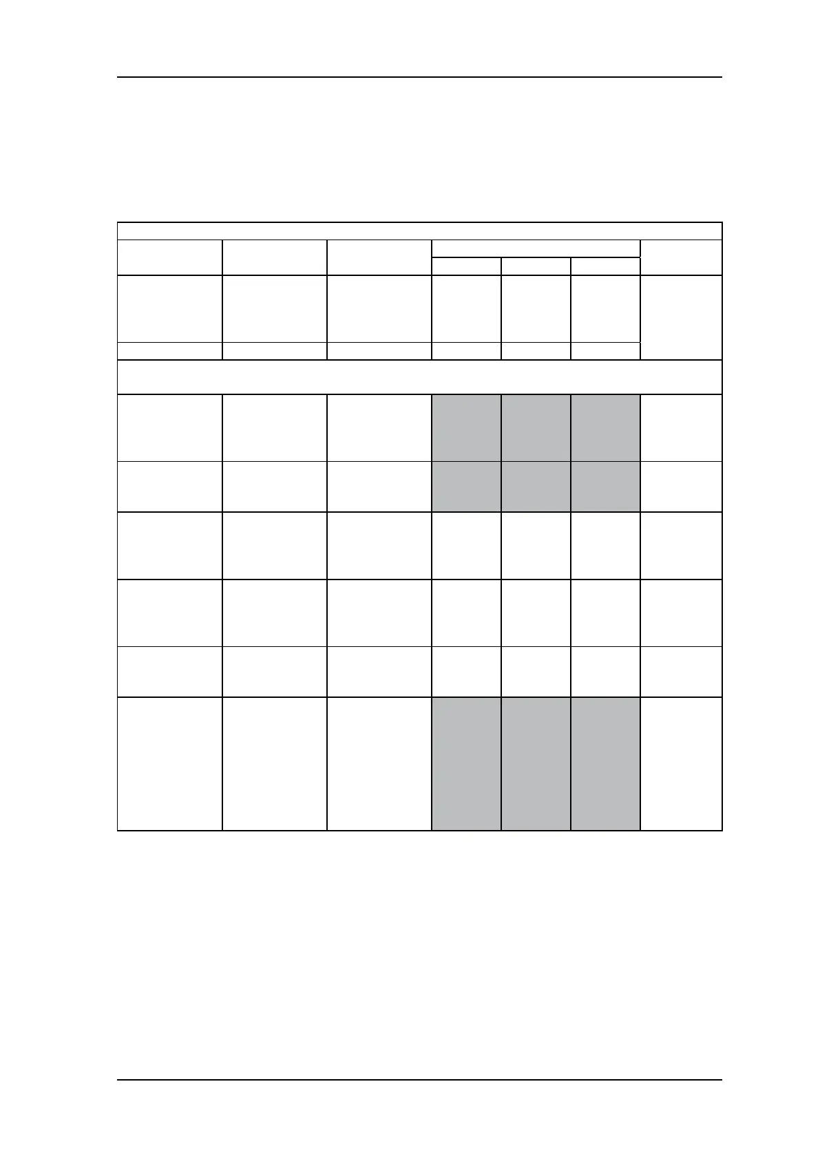
8.2 System Status
Display indications, current output and relay states for various operational conditions
are shown in the following table. For further details of error messages and trouble shooting
see section 12.3.
System Status
Status Display Current Output
Relay
Back
Light
A1 A2 Fault
Fault:
Circuit or sensor
error
F-XX
fault number
with fault icon
blinking
0-1.0 mA
Yellow,
ashing
System Fault N/A 0-0.15mA
Note: In the event of processor failure the watchdog will automatically reset the system for
recovery.
Warning
W-XX
warning number
with fault icon
blinking
Dependent on
system status
Green
Steady
Normal
0.0
Gas
concentration
4-20 mA
Green
Steady
Alarm 1
Gas
concentration.
1
st
alarm icon
blinking
4-20 mA
Red,
ashing
Alarm 2
Gas
concentration.
2
nd
alarm icon
blinking
4-20 mA
Red,
ashing
Over-range
Full scale icon
and reading
blinking
22mA
Red,
ashing
Inhibit
Inhibit icon
dependent
on Menu
command. If
any relay is set
to inhibit relay,
then inhibit relay
will be activated.
2 or 4mA
depending on
conguration.
Green
Steady
Table 4: System status

 Loading...