TB6575/TB8575 SUITEPRO™ DIGITAL FAN COIL THERMOSTATS SETUP
62-0278—01 10
Installer Setup (IS) Mode
Installer Setup Mode allows you to configure the thermostat for
your application.
To enter Installer Setup Mode:
• Press and hold both the System button (labeled Heat/
Cool) and the Up Arrow button for three (3) seconds.
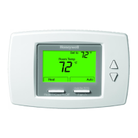
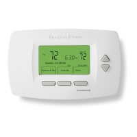
This displays the setup screen on the LCD. See Fig. 25.
NOTE: Exiting Installer Setup Mode is the same as the
method for entering setup mode.
Table 4 provides the setup codes (IS codes) and values. To enter
the setup parameters:
1. Press the System (Heat/Cool) button to cycle through the
IS codes, which display in the upper right following the
word Setup.
2. Press the Up or Down Arrow buttons to cycle through the
option values for the currently displayed IS code. The
values display in the center of the screen.
3. After the desired value displays, press the System button
to store your value selection and display the next IS code.
Fig. 25. Installer Setup (IS) mode screen.
M27585
Setup
Table 4. Installer Setup (IS) Codes and Options.
IS
Code
Code
Description
Option
Value Option Description (Default value shown in Bold) Notes
1 Line Voltage
Selection
0 120 Vac power supply (Default)
1 240 Vac power supply
2 System Type 0 Heat only
1 Cool only
2 Two pipes: Heat or Cool; Manual Changeover
3 Two pipes: Heat or Cool; Seasonal Changeover (requires
optional pipe sensor)
4 Four pipes: Manual Changeover
5 Four pipes: Auto Changeover (Default)
6 Two pipes: Heat or Cool; with Auxiliary Heat (requires optional
pipe sensor).
Allows auxiliary heat to turn on when
pipes have cold water.
7 Four pipes: Manual and Auto Changeover
3 Valve Output
Type
0 N.O. (normally open) – ON/OFF (Default)
1 N.C. (normally closed) – ON/OFF
4 Sensor Type 0 Onboard Sensor (Default)
1 Remote Sensor (TR21 or other 20K Ohm sensor)
5 Pipe Sensor 0 Default mode is Heat:
N.O. (normally open) Input.
Only displays when system type 3 or 6 is selected.
The Pipe Sensor code automatically
displays based on the System Type
(IS code #2) selection. For example,
only when you select the value 3 or 6
for the System Type, will the Pipe
Sensor code and its values display.
• Pipe sensor will flash on display
screen if analog input (#4) is lost.
• Pipe sensor status and water
temperature can be checked in
test mode (see “Installer Test (IT)
Mode” on page 12 for details)
• Pipe sensor incorporates pipe
purge feature (see “Pipe Purge”
on page 13 for details).
1 Default mode is Cool:
N.O. (normally open) Input.
Only displays when system type 3 or 6 is selected.
2 Default mode is Heat:
N.C. (normally closed) Input.
Only displays when system type 3 or 6 is selected.
3 Default mode is Cool:
N.C. (normally closed) Input.
Only displays when system type 3 or 6 is selected.
4 Analog input (Default). NTC20K, whose curve is the same as
TR21.
Only displays when system type 3 or 6 is selected.
6 Pipe Sensor
Threshold
for Cooling
50 to 65 Range is 50°F to 65°F. Default is 60°F. Changes to Cool when pipe
temperature is below threshold.
7 Pipe Sensor
Threshold
for Heating
75 to 90 Range is 75°F to 90°F. Default is 80°F. Changes to Heat when pipe sensor
temperature is above threshold.
8 Temperature
Scale
0 Degrees Fahrenheit (°F); Default.
1 Degrees Celsius (°C).
9 Fan Control
Type
0 User can choose Constant or Cycle (Default)
3-speed (Low > Medium > High) or Auto
When fan is in Auto (using cycle
mode), the fan ramping algorithm is
used.
1 Cycle only (Fan is in Auto mode)
10 Dead Band
for 4-Pipe
Auto
Changeover
2 to 9 Range is 2 to 9. Default is 3 Only displays for four pipe
configurations (system types 4, 5, or
9) and is used for Auto Changeover.
 Loading...