01/06 Kit Instruction 51-52-33-153 3
Replacement Instruction, Continued
Printed wiring board
removal
Table 2 How to Remove the Printed Wiring Boards from the Chassis
Step Action
1
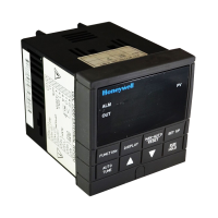
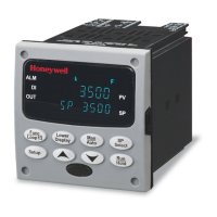
Remove the chassis from the case as shown in Figure 1.
2
Separate the chassis frame at the release points shown in Figure 2
and wiggle each printed wiring board out of its socket on the
display/keyboard assembly. Pull all boards out of the chassis.
3
Remove the wire connectors from plug WG1 on Power/Output
Board. Slide a small screwdriver under the connectors and lift the
release.
4
Lay the printed wiring boards flat on a static-free surface. Use
Figures 3 through 6 to locate the board being replaced.
Figure 2 Removing the Printed Wiring Boards
Printed wiring board
identification
Figure 3 Major Printed Wiring Board Identification
Continued on next page
Release points (top and bottom)
Power / Out
ut Bd.
Auxiliary output / Digital
Inputs / Communication Bd.
MCU / Input Board
O
tional Rela
s Bd.
WG1 and Wires
Display / Keyboard
 Loading...