6 Kit Instruction 51-52-33-153 01/06
Replacement Instruction, Continued
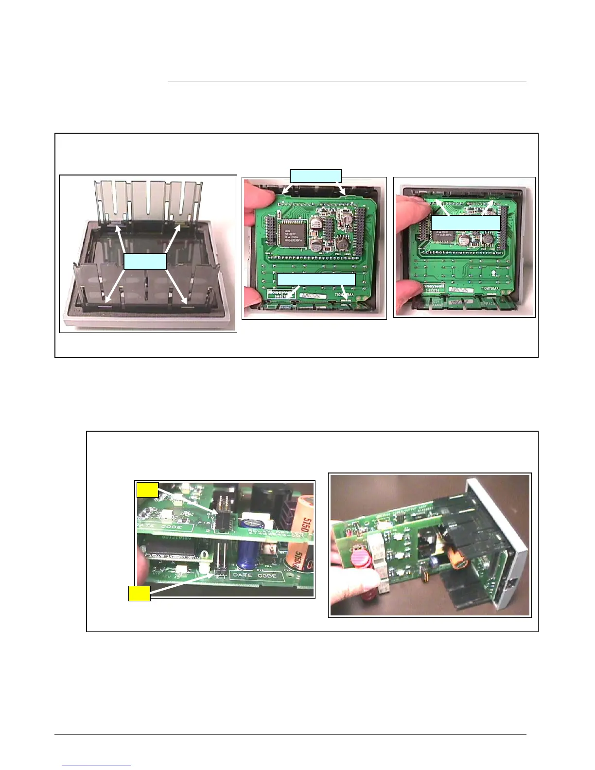
Chassis Reassembly
Figure 7 Display / Keyboard
There are four slots cut in the Bezel which fit four tabs on the Display / Keyboard. Place the bottom of the
Display / Keyboard into the bottom chassis slots and press the top of the display in until it snaps into place in
the top chassis slots.
Chassis Reassembly
Figure 8 Optional Relay and Power/Output Board
The P15 connector on the Optional Relay board plugs into J15 on the Power/Output board. Insert
these boards as an assembly into the Chassis. Start them in the chassis groves and carefully push
them in until they snap into place.
Continued on next page
P15
J15
4 Slots
Top of Display
B
m
f Di
l
Tabs
 Loading...