VideoBloX Quick Start Guide
Rev 1.0 11 Document 900.0840
09/06
Installing the Alarm Termination Box (ATB)
The ATB is shipped with the VideoBloX system and consists of a stainless steel box with a
ribbon cable.
• Support for 32 Alarm Inputs - potential free (dry) contact
• Support for 4 Form C Relays
• Removable Terminal Blocks
Installation
1. Connect the ATB to the VideoBloX CPU using the ribbon cable supplied.
2. Connect a toggle switch or other alarm device to activate the alarm signal to Input #1
of ATB.
3. Connect an output device (lamp or sounder) to the Common/Normally Open of
Output #1 and the appropriate power supply.
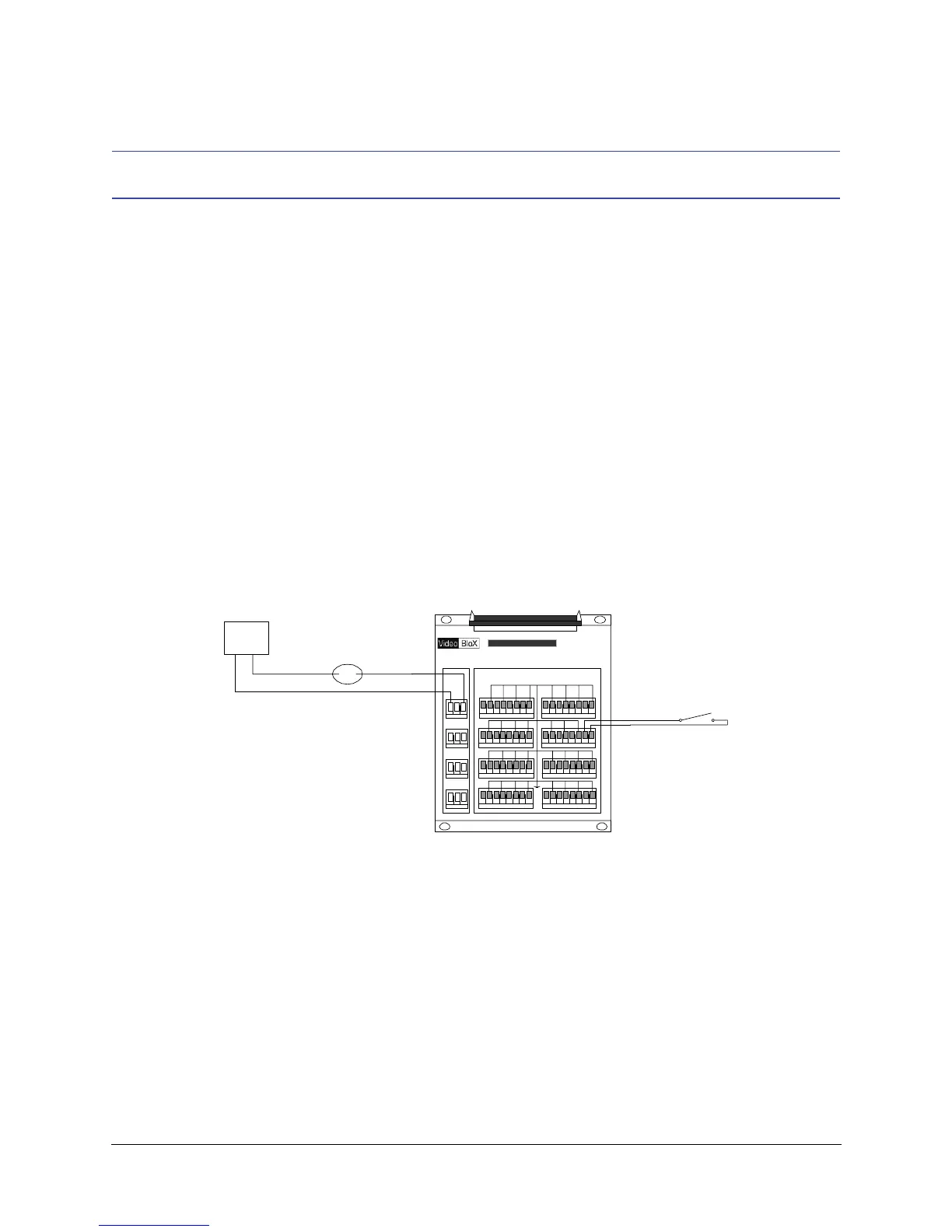
Figure 6 Alarm Terminal Block (ATB) Connections
ALARMTERMINATIONBOX
AlarmInputs
1234 5678
9101112 131415
17 18 19 20 21 242322
25 26 27 28 29 323130
NC
NO
C
NC
NO
OUT2
C
NC
NO
OUT3
C
NC
NO
OUT4
C
RelayOutput s
S
Ribbon Connector
to CPU
External
Power Supply
Controlled
Device
Typical Input
NO/NC Dry Contact
Relay Ratings
1A @ 30 VDC
0.5A @ 24 VAC
Alarm Inputs are
pulled to 5 VDC by
10K resistor.
 Loading...