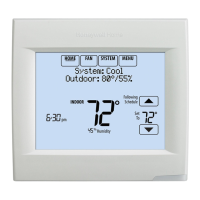
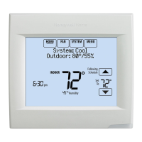
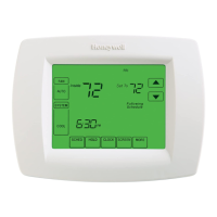
VISIONPRO
®
8000 WITH WI-FI
®
33-00096—01 6
INSTALLATION
Wiring 24 Vac Common
• Single-Transformer System—Connect the common side of
the transformer to the C screw terminal of the thermostat.
Leave the metal jumper wires in place between R and RC.
• Two-Transformer System—Connect the common side of the
cooling transformer to the C screw terminal of the
thermostat. Remove the metal jumper wire between R and
RC. Connect the hot side of heating transformer to R and
connect the hot side of cooling transformer to RC.
Selecting Discharge Air Temperature
Sensor Mounting Locations
Refer to the guidelines below and Fig. 3–7 for mounting
locations of the Discharge Air Temperature Sensor.
Selecting Discharge Air Temperature
Sensor Mounting Location
1. Mount the Discharge Air Temperature Sensor on the
supply duct in a location where the air is mixed well.
Mount the Discharge Air Temperature Sensor out of sight
of the A-Coil/Heat Exchanger when possible. See Fig. 3.
2. When possible, mount the Discharge Air Temperature
Sensor upstream of a Steam Humidifier, a Fan Powered
Humidifier or a Dehumidifier that is ducted to the supply.
See Fig. 4–5.
3. If space does not allow a Discharge Air Temperature
Sensor upstream of a Steam Humidifier or Fan Powered
Humidifier, mount the Discharge Air Temperature Sensor
downstream of the Humidifier. See Fig. 4.
4. If a Bypass Humidifier is installed, mount the Discharge
Air Temperature Sensor downstream of the Bypass
Humidifier. See Fig. 6–7.
Selecting Discharge Air Temperature
Sensor Mounting Location
1. Install the Discharge Air Temperature Sensor on the duct
in a location where the air is mixed well. See Fig. 3–7.
Fig. 3.
Fig. 4.
Model Numbering TH8321
Stages 3H/2C HP
2H/2C CONV
Residential or Commercial
Powered - C Wire (wire saver compatible)
Onboard Humidity Sensor
Number of Universal Relays 1
Number of Universal Sensor Inputs 1
Economizer / TOD Output
MOUNT DISCHARGE
SENSOR HERE
M35768
HEAT
EXCHANGER
BLOWER
VENTILATOR
OR
DEHUMIDIFIER
A-COIL
M35769
HEAT
EXCHANGER
BLOWER
HUMIDIFIER
ALTERNATE MOUNTING LOCATION
FOR DISCHARGE SENSOR.
MOUNT
DISCHARGE
SENSOR HERE
ABOVE
CENTER
OF A-COIL
UPSTREAM OF
HUMIDIFIER
VENTILATOR
OR
DEHUMIDIFIER
 Loading...


