4 Assembly
Linear actuators MC250 • MC253 • MC500 • MC503
14 Version 2.1 - March 2011 Operating Manual
3 Rotate the hexagonal nut M10 (451) wrench size 17 onto the valve spindle (18).
4 Rotate the coupling (3) onto the valve spindle (18).
5 Use the flat hexagonal nut to lock the valve spindle (18) to secure it against
distortion.
6 Place the actuator with traverse (2) onto the valve neck (19).
7 For Types MC253, MC503:
Fix the traverse (2) with a hexagonal nut (459) wrench size 50.
8 For Types MC250, MC500:
Fix the traverse (2) of the actuator with screws (428) wrench size 13 and
retaining washers (308) on the valve neck (19).
9 Use the handwheel (36) to adjust the spindle nut (5) upwards so that the
bolt(315) can be refitted.
10 Fit the blank (314) flange!
Proceed as follows to dismantle the linear actuator:
1 Carry out the installation sequence steps in reverse order.
4.4 Fit/remove cover
The terminals for the electrical connection are located in the cover.
Electric shock due to live components!
If the power supply is switched off, there is danger of electric shock due to live
components.
• Prior to starting work ensure that the actuator is disconnected safely from the
mains power supply.
• Secure against unauthorised switching-on.
• Remove the cover only temporarily.
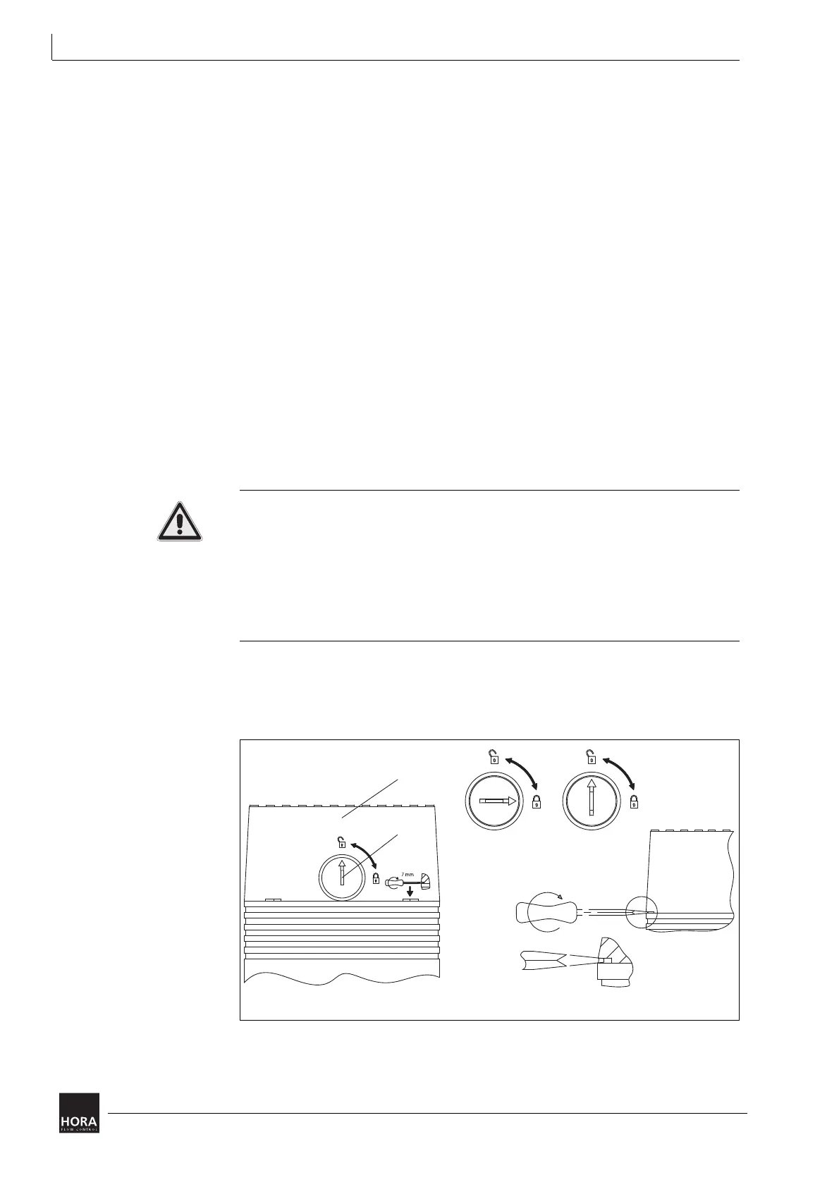
Proceed as follows to remove the cover:
1 Unlock the cover (201). Use a screwdriver (34) to turn the rotary knob counter-
clockwise through 90° as far as the stop.
2 Insert a screwdriver into a groove in the cover and lift off the (201) cover.
34 Knob 201 Cover
Diagram 7 Remove cover

 Loading...