4 Assembly
Linear actuators MC250 • MC253 • MC500 • MC503
18 Version 2.1 - March 2011 Operating Manual
4.5.2 Remove printed circuit board cover
The printed circuit board cover must be removed (33) first in order to adjust the
linear actuator via the coding switches.
Electric shock due to live components!
If the power supply is switched off, there is danger of electric shock due to live
components.
• Prior to starting work ensure that the actuator is disconnected safely from the
mains power supply.
• Secure against unauthorised switching-on.
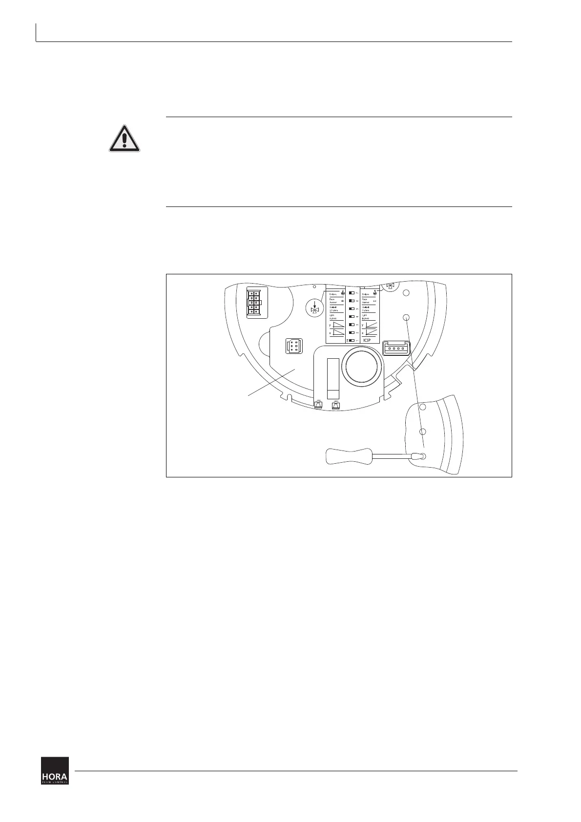
1 Insert a screwdriver into a groove in the cover (201) and lift the (201) cover out.
2 Insert a small screwdriver into the groove provided in the printed circuit board
cover for this purpose(33) and remove it with care.
3 Once the printed circuit board cover(33) has been removed from the actuator
casing, (1) coding switches S1 to S10 will be accessible.
4.6 Optional extras installation
Optional extras are only part of the scope of supply of the linear actuator if
expressly ordered! The linear actuators are prepared for retrofitting the following:
• Way-switch printed circuit board (106)
• Printed circuit board for output signal X=0/4 … 20 mA (111)
2.2 Accessories on page 7
Diagram 10 Remove the printed circuit board cover from the actuator casing.

 Loading...