4 Assembly
Linear actuators MC250 • MC253 • MC500 • MC503
16 Version 2.1 - March 2011 Operating Manual
4 Check the power supply voltage.
If the required tolerance of the power supply voltage cannot be maintained with a
mains transformer, an AC voltage regulator must be used.
2.5 Technical data on page 10.
Proceed as follows to switch the electrics on:
1 Remove the (201) cover.
Proceed as follows to remove the cover: on page 14.
2 Feed the cable through the screw connector in the cover to the terminal strip.
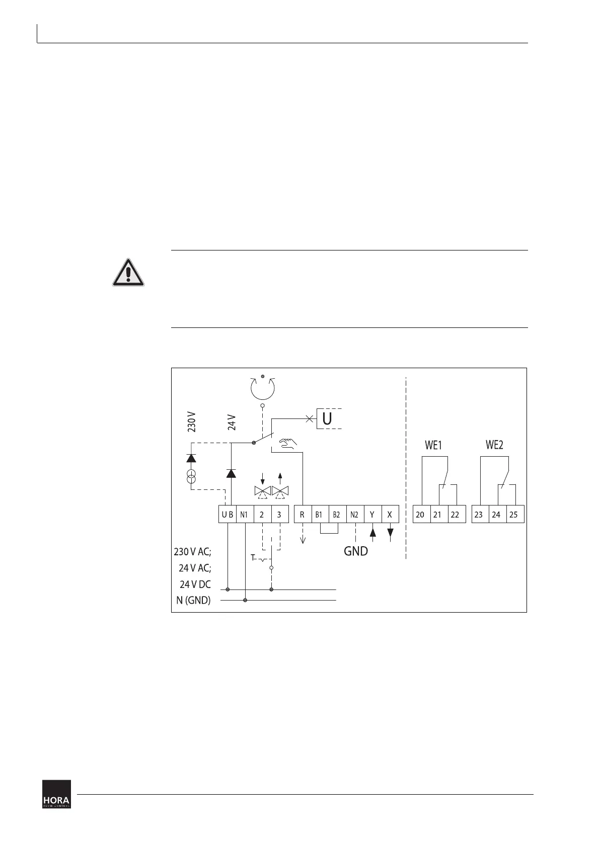
3 Connect the electrics in accordance with the circuit diagram.
Diagram 8 on page 16
Hint: The circuit diagram (481) is located on the printed circuit board cover (33).
Malfunction due to incorrect zero potential!
If the linear actuator is electrically supplied by signal generators with different zero
potentials, this may cause incorrect dynamic performance.
• Ensure that the zero potentials are correctly used.
Table 3 on page 17
4 Tighten the screw connections.
Diagram 8 Wiring diagram

 Loading...