Technical Service Manual M9 Transfer Stretcher (M999-29, Version 11, June 2021) 29
7. SERVICE INSTRUCTIONS
FOOT END ELEVATOR
Summary:
This service instruction outlines the procedure to replace the foot end elevator.
Tools Required:
• 4mm hex key
• 5mm hex key
• 8mm hex key
• torque wrench
• 13mm spanner
• side cutters
• supports
• mallet
Parts Required:
• 2x elevator plugs
• 1x foot end elevator
• 1x standard cable tie
• grease - Shell Cassida Grease EPS 2 or equivalent
• adhesive - Permabond 791 or equivalent (superglue)
• threadlock - Loctite 243 or equivalent
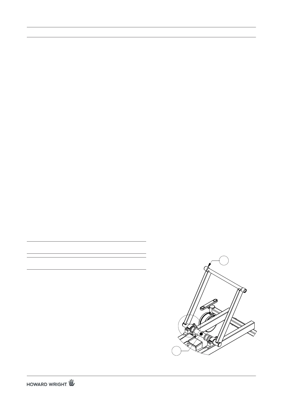
Location:
The foot end elevator is located at the foot end (FE) of the stretcher, connecting the deck to the bogie (see
Figure 12).
CAUTION: When reattaching the earth cable, care should
be taken to ensure correct orientation.
WARNING: Do not attempt to perform any servicing
unless the deck is fully supported.
Procedure:
1. Raise the deck to the maximum height position. Ensure
the deck is flat and apply castor brakes.
2. Lower the deck until all the HI-LO actuator shoulder
bolts have enough clearance to be removed.
3. Unplug the stretcher from the mains supply.
4. Remove the plastic bogie cover and set aside.
5. Safely support both ends of the deck, ensuring the
supports take the full weight.
6. Remove the cable tie securing the earth cable to the
elevator axle (A), then disconnect using a 4mm hex
key.
B
A
F
Figure 12. Foot end elevator