24 Technical Service Manual M9 Transfer Stretcher (M999-29, Version 11, June 2021)
7. SERVICE INSTRUCTIONS
HILO LIFT ACTUATOR
Summary:
This service instruction outlines the procedure to replace either the head end or foot end HI-LO lift actuator.
Tools Required:
• 5mm hex key
• 13mm spanner
• side cutters
• supports
• small flat blade screwdriver
Parts Required:
• 1x HI-LO actuator
• 2x M8 nyloc nuts
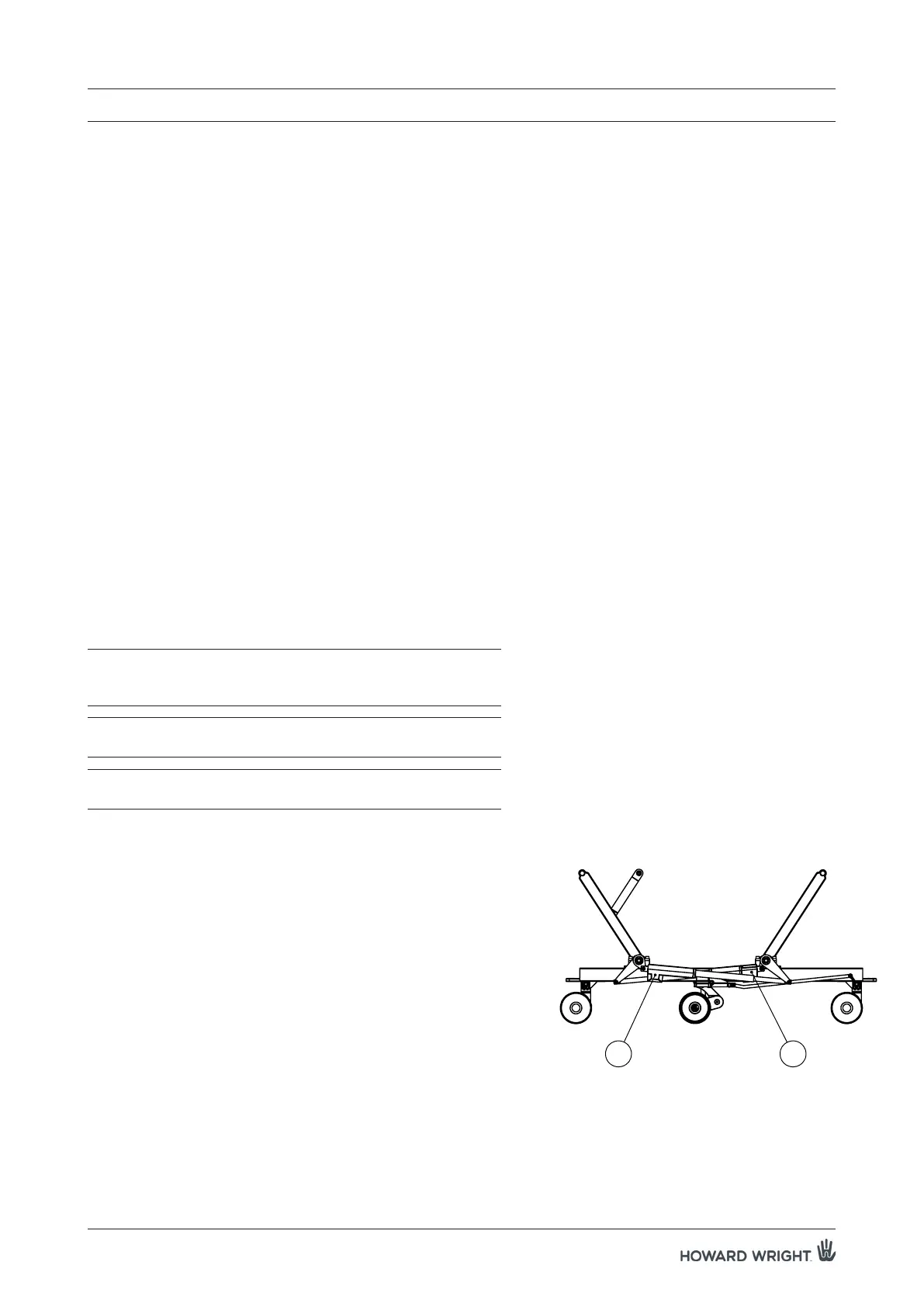
Location:
There are two HI-LO lift actuators, the head end (HE) actuator and foot end (FE) actuator. They are located
underneath the bogie cover.
WARNING: Ensure the actuator cables are secured away
from moving parts, but allowing sufficient length
for elevator movement.
WARNING: Do not attempt to perform any servicing unless
the deck is fully supported.
WARNING: Ensure all shoulder bolts are securely fitted with
new nyloc nuts.
Procedure:
1. Raise the deck to the maximum height position. Ensure the
deck is flat and apply castor brakes.
2. Unplug the stretcher from the main mains supply.
3. Remove the plastic bogie cover and set aside.
NOTE: If the failed actuator does not allow the deck
to be raised or lowered, then the stretcher can
be carefully laid on its side (two person lift) for
access to actuators.
Orientate the castors towards the direction of
tipping and apply the castor brakes before lifting
(see figure 9).
4. Remove plug locator securing the cable plug to the
actuator.
5. Safely support both ends of the deck, ensuring the
supports take the full weight, unless the stretcher is on its
side.
6. Using a small flat blade screwdriver, remove the cable
locking ring by pushing in the retainer clips either side of
Figure 8. Identification of HI-LO actuators.
FE
HE