Mode1209A
3·1.
INTRODUCTION.
SECTION
III
OPERATING
INSTRUCTIONS
3-8.
BALANCE.
Section III
3-2. This section contains information
as
an aid
to
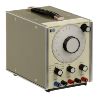
operating the Model 209A. Included are control and
connector descriptions (Figure 3-1), and some special
operating considerations.
3-3.
TURN
ON
PROCEDURE.
34.
To turn on the Model 209A, proceed
as
follows:
a.
Set the two-position voltage selector switch
on the rear panel
to
the value
of
available
line voltage.
b. Connect the
AC
power cord to line voltage.
c.
Switch the RANGE switch from OFF
to
the
desired frequency range.
d. Select the desired frequency and voltage
output
with the frequency dial and
amplitude controls respectively.
3-5.
OPERATING
CONSIDERATIONS.
3-6.
FLOATING
OUTPUT.
WHEN
THE GROUND STRAP
ON
THE
REAR
PANEL
IS
CONNECTED, INPUT GROUND
IS
AT
EARTH
GROUND
POTENTIAL.
3-7.
When
the ground strap on the rear
of
the Model
209A
is
disconnected, the chassis
is
isolated from
power ground. The outputs may then
be
connected
to any point with a dc potential
of
not more than
+/-500 volts.
If
a dc voltage up to +/-500 volts
is
connected between the ground connectors on the rear
panels, the oscillator output
is
dc offset by that
amount.
3-9. With the chassis isolated from the cabinet, the
sine wave output will be balanced to greater than 40
dB
at
frequencies below 20 kHz.
If
the square
wave
output
is
being used simultaneously with the black
terminal connected to ground, the sine wave output
will no longer be balanced.
3-10.
SYNCHRONIZATION.
3-11. The Model 209A
is
equipped with a
SYNC
terminal that provides a sync output signal or accepts
a synchronizing input signal from an external source.
The sync output signal
is
a 1.7 volt rms sine
wave
in
phase with the oscillator output. The external sync
signal can be any periodic waveform
of
sufficient
amplitude to maintain sync. For an external sync
signal with an amplitude
of
5 volts rms, the oscillator
will remain synchronized at frequencies
of
+/-7%
of
the set frequency.
3-12. The Model 209A can be synchronized to any
significant harmonic
of
an external signal. However,
if
a harmonic or non-sinusoidal waveform
is
used
to
synchronize the Model 209A, some portion
of
the
external sync signal will be
on
the output. This small
signal will appear
as
distortion. The amount
of
this
apparent distortion will be directly proportional
to
the amplitude
of
the sync signal. For a non-sinusoidal
sync input
of
2 volts peak-to-peak, the distortion will
be down about
45
dB
for frequencies which are
normally down -60 dB.
3-13.
LOW
DISTORTION.
3-14. At frequencies below 100 Hz, distortion can be
reduced by switching the NORM/LOW DIST switch
on the rear panel
to
LOW
DIST. In the
LOW
DIST
mode
the
Model 209A will have a longer settling time
when changing frequencies. To avoid this, set the
desired frequency before switching to
LOW
DIST.
3-1
www.HPARCHIVE.com