Section V
5-9.
OUTPUT
VOLTAGE
AND
IMPEDANCE
CHECK
(SINEWAVE).
a.
Connect the Model 209A sine
wave
output
without a 600 ohm load to the
AC
Voltmeter.
b. Set the
AC
Voltmeter
to
the 10V RANGE,
and the Model 209A sine
wave
amplitude to
maximum at a frequency setting
of
20 kHz.
c.
The meter should indicate at least 10 V rms.
d. Reduce the 209A output to 10 V rrns.
e.
Connect a 600 ohm load to the Model 209A.
f.
The
AC
Voltmeter should indicate 5 volts
rms,
verifying
the
output
voltage
specification and
an
approximate output
impedance
of
600 ohms.
5-10.
OUTPUT
CONTROL
CHECK
(SINE
WAVE).
a.
Connect the Model 209A sine
wave
output
without a 600 ohm load to the
AC
Voltmeter.
b. Adjust the Model 209A sine
wave
amplitude
to minimum.
c.
The meter indication should be
less
than I
volt rms.
hp209A
OSCILLATOR
Model209A
5-11.
BALANCE
CHECK
(SINE
WAVE).
a.
Connect the Model 209A sine wave output
with a 600 ohm load
to
the
AC
Voltmeter.
b. Set controls
as
follows:
Mode1209A:
Dial 2
RANGE XIOK
AC
Voltmeter:
RANGE ODB
c.
Adjust the Model 209A sine
wave
amplitude
for a meter indication
of
0
dB.
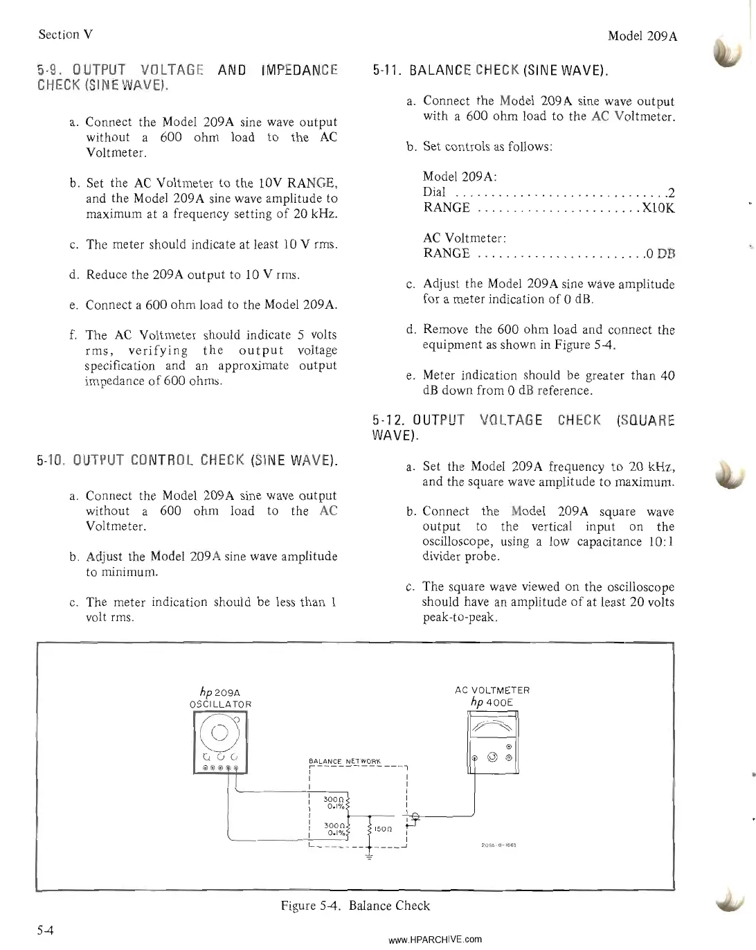
d. Remove the 600 ohm load and connect the
equipment
as
shown in Figure
54.
e.
Meter indication should be greater than 40
dB
down from 0
dB
reference.
5-12.
OUTPUT
VOLTAGE
CHECK
(SQUARE
WAVE).
a.
Set the Model 209A frequency
to
20 kHz,
and the square
wave
amplitude
to
maximum.
b. Connect the Model 209A square
wave
output to the vertical input on the
oscilloscope, using a low capacitance 10: I
divider probe.
c.
The square
wave
viewed on the oscilloscope
should have an amplitude
of
at least 20 volts
peak-to-peak.
AC VOLTMETER
hp
400E
@
~
@
v(;(;
BALANCE NETWORK
@
®
@@@
Hi)
,------------1
l
: I
I I
I
3000
I
0.1%
I
I~
L_~g3~
___
1~::j.T
209A-e-166~
Figure 5-4. Balance Check
54
www.HPARCHIVE.com