DC
NULL
VOLTMETER
hp
419A
Section V
@
D00
'i>@@'i>'i>
I I
I I
I
,----------
,---------
209A-B-I662
THERMAL
CONVERTER
hp
H08-II049A
BUCKING SUPPLY
r--------------,
I I
I I
I
6500n
I
I I
I
~on
I
I I
I
1.34V
I
I I
I I
'-------~~50Il
I
I
I I
~--------------~
Mode1209A
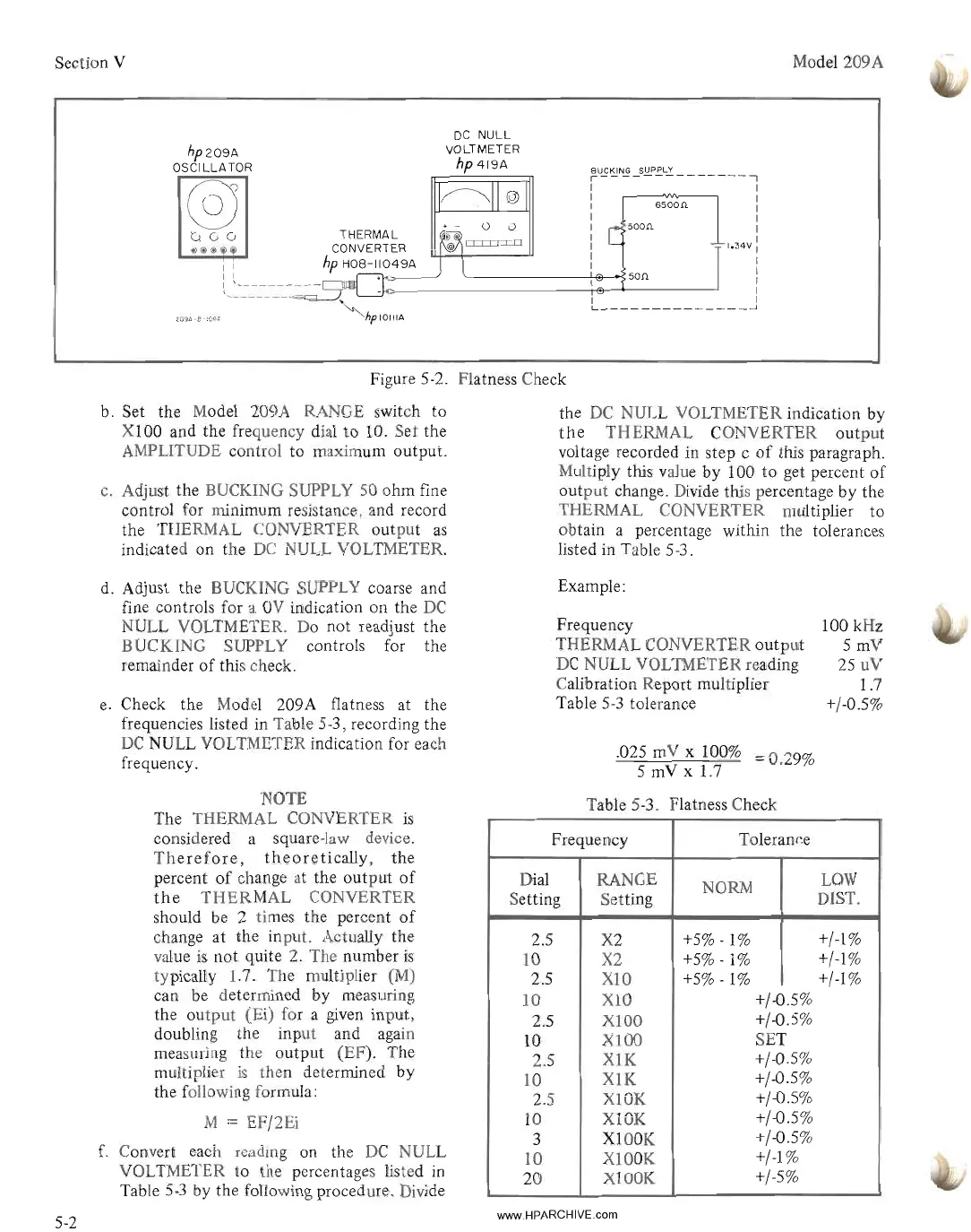
Figure 5-2. Flatness Check
b. Set the Model 209A RANGE switch to
XlOO
and the frequency dial
to
10. Set the
AMPLITUDE control to maximum output.
c.
Adjust the BUCKING SUPPLY 50 ohm fine
control for minimum resistance, and record
the THERMAL CONVERTER output
as
indicated on the
DC
NULL VOLTMETER.
the
DC
NULL VOLTMETER indication by
the
THERMAL CONVERTER output
voltage recorded in step c
of
this paragraph.
Multiply this value by 100
to
get percent
of
output change. Divide this percentage by the
THERMAL CONVERTER multiplier to
obtain a percentage within the tolerances
listed in Table 5-3.
d. Adjust the BUCKING SUPPLY coarse and
fine controls for a
OV
indication on the
DC
NULL VOLTMETER. Do not readjust the
BUCKING SUPPLY controls for the
remainder
of
this check.
e.
Check the Model 209A flatness at the
frequencies listed in Table 5-3, recording the
DC
NULL VOLTMETER indication for each
frequency.
Example:
Frequency
THERMAL CONVERTER output
DC
NULL VOLTMETER reading
Calibration Report multiplier
Table
5-3
tolerance
.025 mV x 100%
= 0.29%
5 mV
x 1.7
100 kHz
5mV
25
uV
1.7
+/-0.5%
5-2
NOTE
The THERMAL CONVERTER
is
considered a square-law device.
Therefore,
theoretically,
the
percent
of
change at the output
of
the
THERMAL
CONVERTER
should be 2 times the percent
of
change at the input. Actually the
value
is
not quite 2. The number
is
typically 1.7. The multiplier
(M)
can be determined
by
measuring
the output (Ei) for a
given
input,
doubling the input and again
measuring the output (EF). The
multiplier
is
then determined by
the following formula:
M
= EF/2Ei
f.
Convert each reading on the
DC
NULL
VOLTMETER
to
the percentages listed
in
Table
5-3
by the following procedure. Divide
Table 5-3. Flatness Check
Frequency
Toleran~e
Dial RANGE
NORM
LOW
Setting Setting
mST.
2.5
X2
+5%
-1% +/-1%
10
X2
+5%
-1%
+/-1%
2.5 X10
+5%
-1%
+/-1%
10
X10
+/-0.5%
2.5
X100
+/-0.5%
10
X100
SET
2.5
XlK
+/-0.5%
10
X1K
+/-0.5%
2.5 XlOK
+/-0.5%
10
XlOK
+/-0.5%
3
XlOOK
+/-0.5%
10 X100K
+/-1
%
20
X100K
+/-5%
www.HPARCHIVE.com