Section III
Model209A
2
SYNC
""""
I
"'AX
6000
3
9
10
,",-LINE
SELECTOR
o
~
IIS/230V±
10%
48-440""
TVA
MAX
CHANGE
FREQ.
SLOWLY
I
,OW
NORM OISl.
""
~~~
~
~ ~
CD
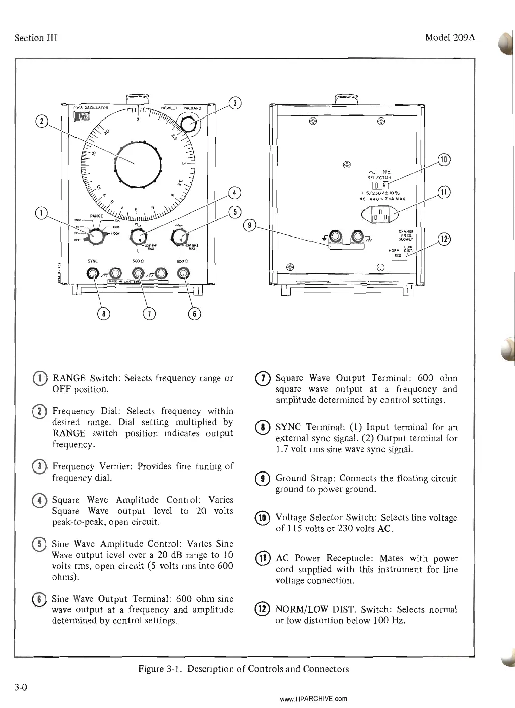
RANGE Switch: Selects frequency range or
OFF position.
eD
Frequency Dial: Selects frequency within
desired range. Dial setting multiplied by
RANGE switch position indicates output
frequency.
o Frequency Vernier: Provides fine tuning
of
frequency dial.
o Square
Wave
Amplitude Control: Varies
Square
Wave
output level to 20 volts
peak-to-peak, open circuit.
eD
Sine
Wave
Amplitude Control: Varies Sine
Wave
output level over a 20
dB
range to 10
volts rms, open circuit (5 volts rms into 600
ohms).
CD
Sine
Wave
Output Terminal: 600 ohm sine
wave
output at a frequency and amplitude
determined
by
control settings.
CD
Square
Wave
Output Terminal: 600 ohm
square
wave
output at a frequency and
amplitude determined by control settings.
CD
SYNC
Terminal: (1) Input terminal for an
external sync signal. (2) Output terminal for
1.7 volt rms sine
wave
sync signal.
CD
Ground Strap: Connects the floating circuit
ground to power ground.
® Voltage Selector Switch: Selects line voltage
of
115 volts or 230 volts
AC.
®
AC
Power Receptacle: Mates with power
cord supplied with this instrument for line
voltage connection.
@ NORM/LOW DIST. Switch: Selects normal
or low distortion below 100 Hz.
Figure 3-1. Description
of
Controls and Connectors
3-0
www.HPARCHIVE.com