Model209A
Section IV
SECTION
IV
THEORY
OF
OPERATION
4-1.
INTRODUCTION.
4-2. This section contains a description
of
the basic
principles
of
circuit operation for the Model 209A.
The information
is
presented
as
a discussion
of
each
block indicated on the Block Diagram, Figure 4-1,
and detailed circuit descriptions which refer to Figure
7-1
and 7-2.
4-3. The Model 209A
is
basically a
Wien
bridge
oscillator. The output from the oscillator circuit
is
applied to a buffer amplifier and to a sine wave
to
square wave converter. These two circuits provide
independent sine
wave
and square wave outputs,
respectively.
4-4.
BLOCK
DIAGRAM
DESCRIPTION.
furnished
through the frequency determining
network
of
CIA,
R8, CIB, and R16. At the
frequency that the phase
of
the positive feedback
is
0
0
,
Xc = R and the maximum ratio
of
output
voltage
is
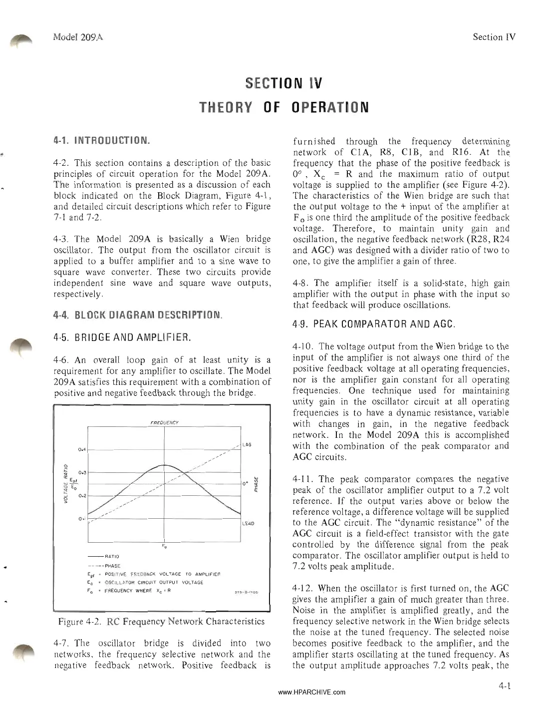
supplied to the amplifier (see Figure 4-2).
The characteristics
of
the
Wien
bridge are such that
the output voltage to the
+ input
of
the amplifier at
F
0
is
one third the amplitude
of
the positive feedback
voltage. Therefore, to maintain unity gain and
oscillation, the negative feedback network (R28, R24
and AGC) was designed with a divider ratio
of
two to
one, to
give
the amplifier a gain
of
three.
4-8. The amplifier itself
is
a solid-state, high gain
amplifier with the output in phase with the input so
that feedback will produce oscillations.
4-9.
PEAK
COMPARATOR
AND
AGC.
-RATIO
FREQUENCY
4-5.
BRIDGE
AND
AMPLIFIER.
4-10. The voltage output from the
Wien
bridge to the
input
of
the amplifier
is
not always one third
of
the
positive feedback voltage at
all
operating frequencies,
nor
is
the amplifier gain constant for all operating
frequencies. One technique used for maintaining
unity gain in the oscillator circuit at
all
operating
frequencies
is
to have a dynamic resistance, variable
with changes in gain, in the negative feedback
network. In the Model 209A this
is
accomplished
with the combination
of
the peak comparator and
AGC
circuits.
4-12. When the oscillator
is
first turned on, the
AGC
gives
the amplifier a gain
of
much greater than three.
Noise in the amplifier
is
amplified greatly, and the
frequency selective network in the
Wien
bridge selects
the noise at the tuned frequency. The selected noise
becomes positive feedback to the amplifier, and the
amplifier starts oscillating at the tuned frequency.
As
the output amplitude approaches 7.2 volts peak, the
4-11. The peak comparator compares the negative
peak
of
the oscillator amplifier output to a 7.2 volt
reference.
If
the output varies above or below the
reference voltage, a difference voltage will be supplied
to the
AGC
circuit. The "dynamic resistance"
of
the
AGe
circuit
is
a field-effect transistor with the gate
controlled
by
the difference signal from the peak
comparator. The oscillator amplifier output
is
held to
7.2 volts peak amplitude.
LEAD
LAG
-
-
/
-
-
/
/
.".......-
-.........
/
/
-
/
/
//~
/
/
-
-
""
-
-
~//
/
~
I
-
-----
PHASE
E
pf
s POSITIVE FEEDBACK
VOLTAGE
TO
AMPLIFIER
Eo " OSCILLATOR CIRCUIT OUTPUT VOLTAGE
F0 " FREQUENCY WHERE Xc
11
R
0.4
o.
Figure 4-2.
RC
Frequency Network Characteristics
4-6.
An
overall loop gain
of
at least unity
is
a
requirement for any amplifier to oscillate. The Model
209A satisfies this requirement with a combination
of
positive and negative feedback through the bridge.
4-7. The oscillator bridge
is
divided into two
networks, the frequency selective network and the
negative feedback network. Positive feedback
is
4-1
www.HPARCHIVE.com