9
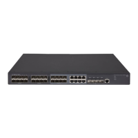
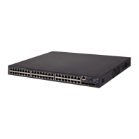
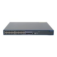
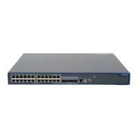
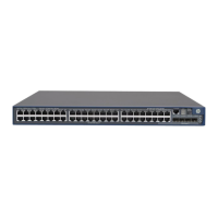
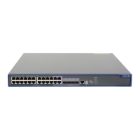
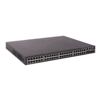
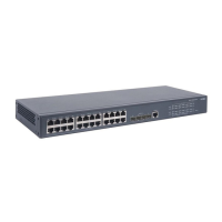
Table 4 Mounting brackets provided with the switch
Switch model Mounting brackets Views
• HP 5130-24G-4SFP+ EI
• HP 5130-24G-4SFP+ EI TAA
One pair of 1U two-hole mounting
brackets
See Figure 2.
• HP 5130-24G-PoE+-4SFP+ (370W) EI
• HP 5130-24G-PoE+-4SFP+ (370W) EI TAA
• HP 5130-48G-4SFP+ EI
• HP 5130-48G-4SFP+ EI TAA
• HP 5130-48G-PoE+-4SFP+ (370W) EI
• HP 5130-48G-PoE+-4SFP+ (370W) EI TAA
• HP 5130-24G-SFP-4SFP+ EI
• HP 5130-24G-SFP-4SFP+ EI TAA
One pair of 1U four-hole mounting
brackets
See Figure 3.
Figure 2 1U two-hole mounting bracket
(1) Screw hole for attaching the bracket to the switch
(2 ) Screw hole for attaching the bracket to the rack
post
Figure 3 1U four-hole mounting bracket
(1) Screw hole for attaching the bracket to the switch
(2 ) Screw hole for attaching the bracket to the rack
post
Attaching the mounting brackets to the switch
The HP 5130-24G-4SFP+ EI, HP 5130-24G-4SFP+ EI TAA, HP 5130-24G-PoE+-4SFP+ (370W) EI,
H P 513 0 -24 G - Po E + - 4 S F P + ( 370 W ) E I TA A , H P 513 0 - 4 8 G - 4 S F P + E I , a n d H P 513 0 - 4 8 G - 4 S F P + E I TA A
switches provide two mounting positions: one front mounting position (near the network ports) and one
rear mounting position (near the power supplies).
1
2
 Loading...
