48
Product code HP description Max transmission distance
JD096C HP X240 10G SFP+ SFP+ 1.2m DA Cable 1.2 m (3.94 ft)
JD097C HP X240 10G SFP+ SFP+ 3m DA Cable 3 m (9.84 ft)
JG081C HP X240 10G SFP+ SFP+ 5m DA Cable 5 m (16.40 ft)
NOTE:
HP recommends that you use HP 1000 Mbps SFP transceiver modules, SFP+ transceiver modules, or SFP+
cables for the SFP+ ports on the switch. The HP 1000 Mbps SFP and SFP+ transceiver modules are subjec
to change over time. For the most up-to-date list of SFP and SFP+ transceiver modules, contact your HP
sales representative or technical support engineer.
For more information about the 1000 Mbps SFP transceiver modules, SFP+ transceiver modules, and
SFP+ cables, see HP Comware-Based Switches Transceiver Modules User Guide.
Figure 49 SFP+ cable
(1) Connector (2) Pull latch
Combo interface
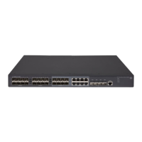
T h e H P 513 0 -24 G - S F P- 4 S F P + E I / H P 513 0 -24 G - S F P- 4 S F P + E I TA A s w i t c h p r o v i d e s e i g h t c o m b o i n t e r f a c e s .
A combo interface includes an SFP port and a 10/100/1000Base-T auto-sensing Ethernet port. Only
one of these two ports can operate at a time.
LEDs
System status LED
The system status LED shows the operating status of the switch.
Table 17 System status LED description
LED mark Status Description
SYS
Steady green The switch is operating correctly.
Flashing green The switch is performing power-on self test (POST).
Steady red POST has failed.
Flashing yellow Some ports have failed to pass POST.
 Loading...
