EasyManuals Logo

HP 525 Installation Guide

HP 525
26 pages
To Next Page IconTo Next Page
To Previous Page IconTo Previous Page
Page #10 background imageLoading...
Page #10 background image
7
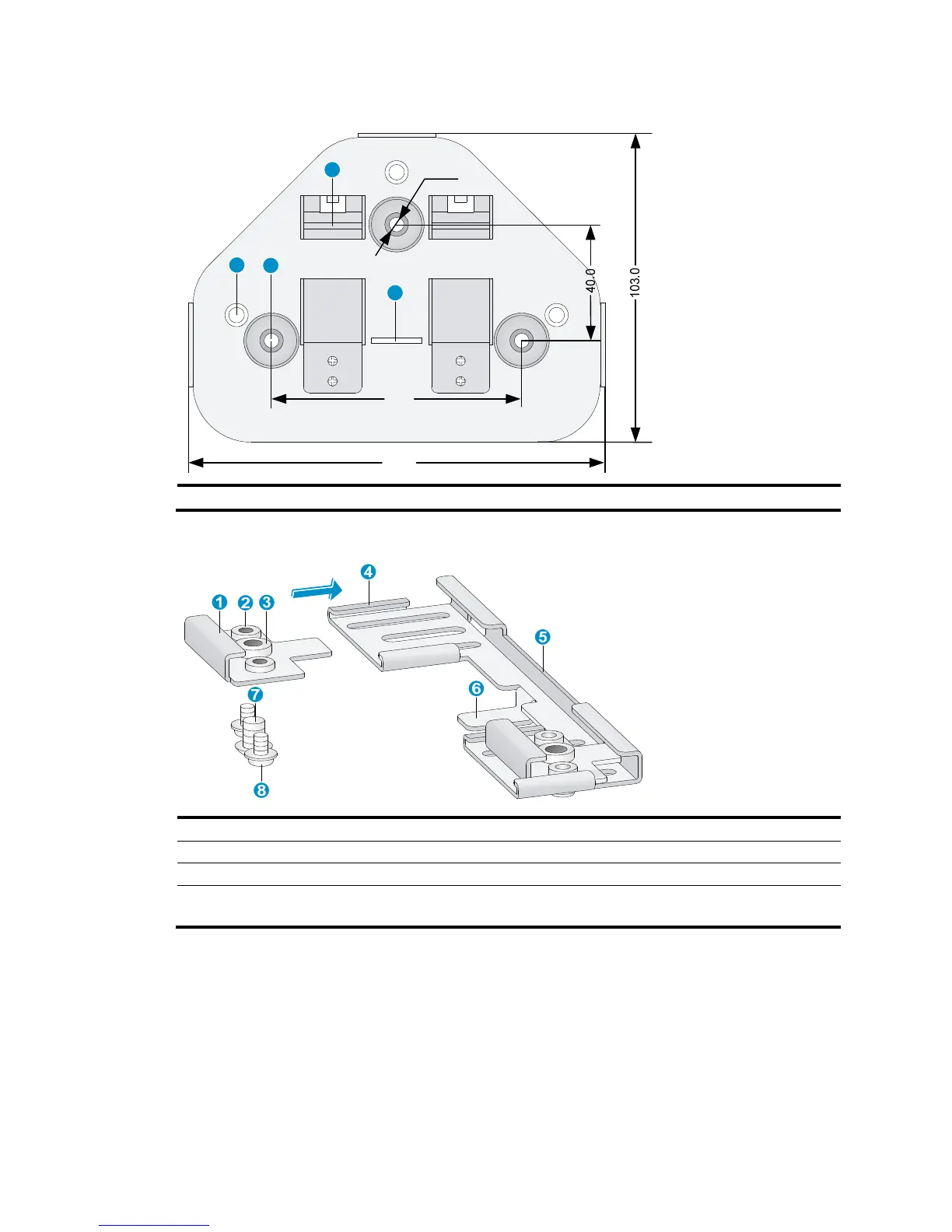
Figure 7 Screw hole locations and sizes (in mm)
(1) Hook (2) Mountin
g
hole
(3) Clip
(4) Mountin
g
clip
Figure 8 T-rail holder
(1) T-rail clip (2)
M3 screw nut
(3) M4 screw nut (4)
Clip holder
(5) T-rail holder (6) Mounting hook
(7) M4 × 5 screw, Length ( 7.6mm / 0.3in ), Wrench
size ( 7mm / 0.28in ), Thread size ( 4mm / 0.16in )
(8) M3 × 8 screw, Length ( 10mm / 0.39in ), Wrench
size
( 5.5mm / 0.22in ),
Thread
size
( 3 mm / 0.12in )
To mount the AP to a ceiling T-rail:
1. Loosen the two M3 × 8 screws on each clip holder. Do not remove the screws.
2. Adjust the T-rail clips to make the T-rail holder wider than the T-rail. See callout 1 in Figure 9. T
hen
lock the T-rail with the T-rail holder according to the arrow indicated in callout 2 in Figure 9.
Ø5.0
86.0
136.0
1
2
4
3

Other manuals for HP 525

Questions and Answers:

Question and Answer IconNeed help?

Do you have a question about the HP 525 and is the answer not in the manual?

HP 525 Specifications

General IconGeneral
Device TypeWireless Access Point
Frequency Band2.4 GHz and 5 GHz
Ethernet Ports1
Wireless Protocol802.11a/b/g/n
Ports1 x 10/100/1000 Ethernet port
PoE802.3af
Antennas2 internal antennas
Security FeaturesWPA, WPA2
Power SourcePoE or External Power Adapter
Operating Temperature0°C to 40°C (32°F to 104°F)
Dimensions5.7 x 5.7 x 1.3 inches (145 x 145 x 33 mm)

Related product manuals