8
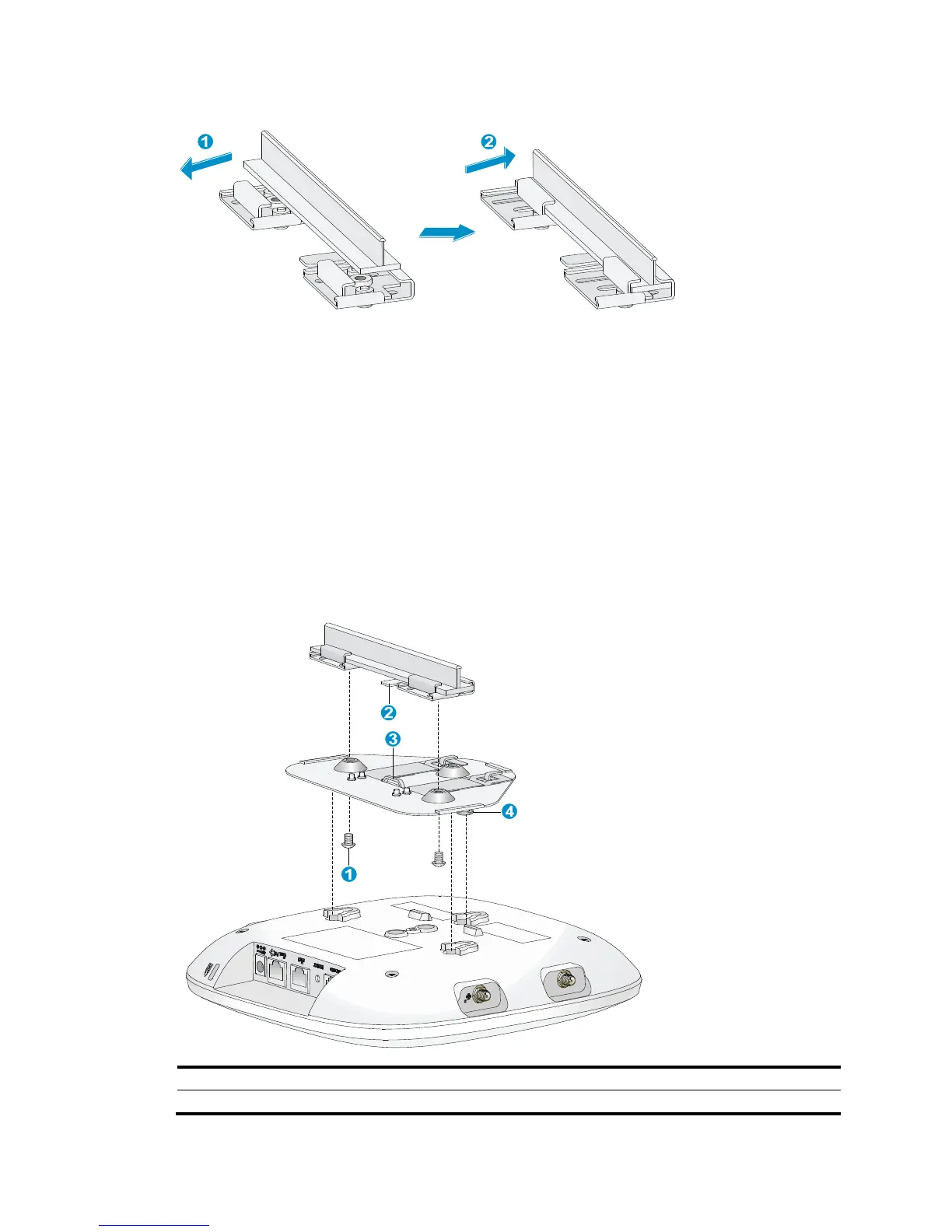
Figure 9 Attaching the T-rail holder to the T-rail
3. Tighten the four M3 × 8 screws on the two clip holders.
4. Verify that the T-rail holder is attached to the T-rail.
5. Hook the mounting clip (see callout 3 in Figure 10)
of the wall-mounting bracket to the mounting
hook (see callout 2 in Figure 10) of the
T-rail holder.
6. Insert the two M4 × 5 screws (see callout 1 in Figure 10) throug
h the two 5 mm (0.20 in) diameter
holes on the wall-mounting bracket according to the dashed line shown in Figure 10. Attach the
sc
rews to the T-rail holder.
7. Verify that the wall-mounting bracket is attached to the T-rail.
8. Connect the AP to the network by using an Ethernet cable.
9. Install the AP to the wall-mounting bracket. For more information, see "Mounting the AP on a wall."
Figure 10 Mounting the AP to the T-rail
(1) M4 × 5 screw, Len
 Loading...