•
•
•
HP
5384A and
HP
5385A
Service
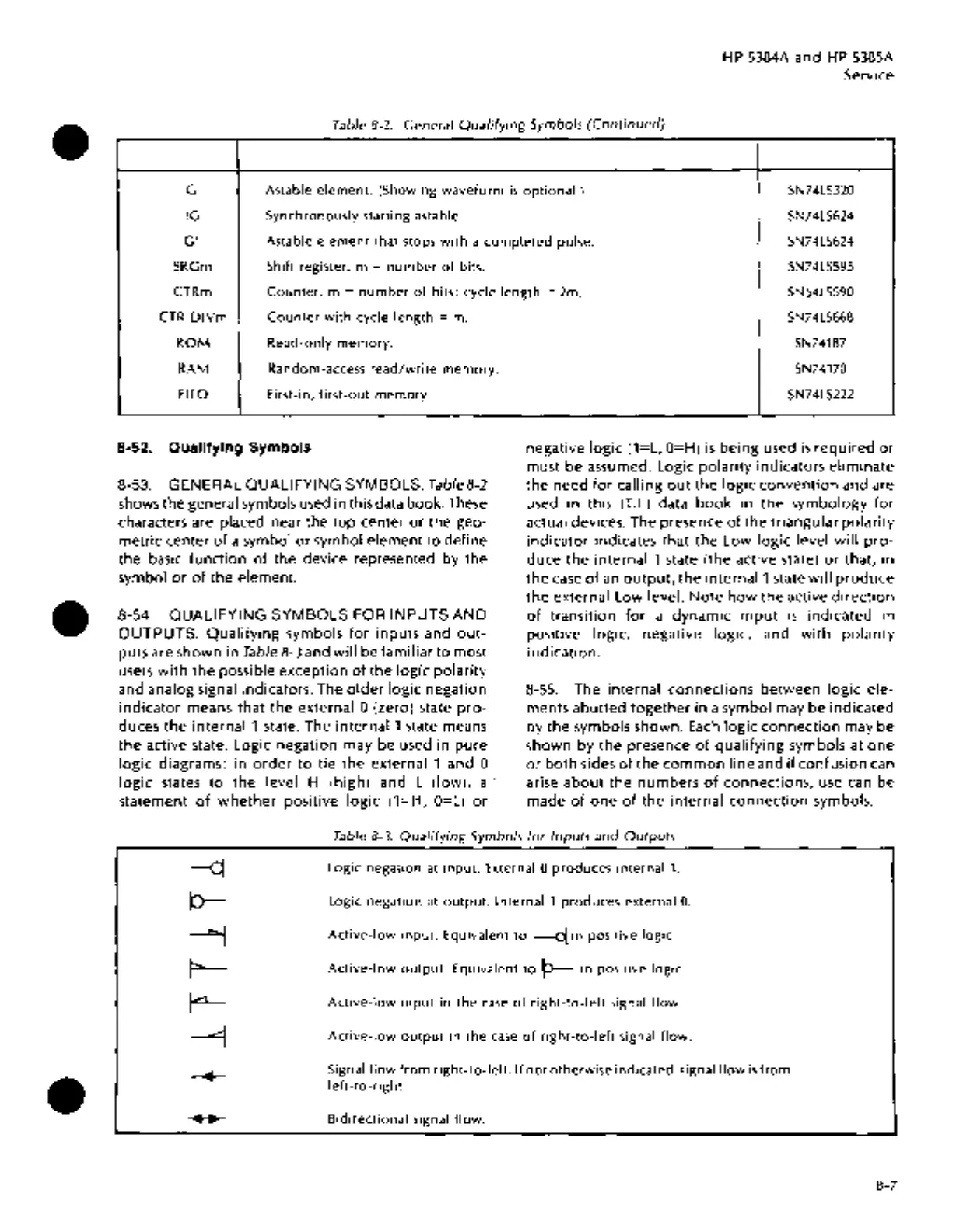
Table 8-2. General
Qualifying
Symbols
(Continued)
G Astable
element.
(Showing
waveform
is
optional.)
SN74LS320
!G
Synchronously starting astable.
SN74LS624
G! Astable
element
that stops
with
a
completed
pulse.
SN74LS624
SRGm
Shift register. m =
number
of
bits.
SN74LS595
CTRm
Counter.
m =
number
of
bits; cycle length = 2m.
SN54LS590
CTR
DIVm
Counter
with
cycle
length
= m.
ROM
Read-only
memory.
RAM
Random-access
read/write
memory.
FIFO
First-in,
first-out
memory.
8-52. Qualifying Symbols
8-53. GENERAL QUALIFYING SYMBOLS.
Tab/eB-2
shows the general symbols used in this data book. These
characters are placed near the top center
or
the geo-
metric center
of
a symbol
or
symbol element
to
define
the basic function
of
the device represented by the
symbol
or
of
the element.
8-54. QUALIFYING SYMBOLS FOR INPUTS AND
OUTPUTS.
Qualifying
symbols
for
inputs and
out-
puts are shown in
Table
8-3
and
will
be familiar
to
most
users
with
the possible exception
of
the
logic
polarity
and analog signal indicators. The
older
logic negation
indicator means that the external 0 (zero) state
pro-
duces the
internal
1 state. The
internal1
state means
the active state. Logic negation may be used in pure
logic
diagrams;
in
order
to
tie
the external 1 and 0
logic states
to
the level H (high) and L (low}, a ·
statement
of
whether
positive logic (1=H,
O=L)
or
SN74LS668
SN74187
SN74170
SN74LS222
negative
logic
(1=L,
O=H)
is
being used
is
required
or
must be assumed. Logic polarity indicators eliminate
the
need
for
calling
out
the
logic
convention
and are
used in this
(T.I.) data
book
in
the
symbology
for
actual devices. The presence
of
the triangular polarity
indicator indicates that
the
Low
logic
level
will
pro-
duce
the
internal 1 state (the active state)
or
that, in
the
case
of
an
output,
the
internal1
state will
produce
the external Low level.
Note
how
the
active
direction
of
transition
for
a dynamic
input
is
indicated in
positive logic, negative logic, and
with
polarity
indication.
8-55. The internal connections between logic ele-
ments abutted
together
in a symbol may be indicated
by the symbols shown.
Each
logic
connection
may be
shown by the presence
of
qualifying
symbols at
one
or
both
sides
of
the
common
line and
if
confusion can
arise
about
the numbers
of
connections, use can be
made
of
one
of
the internal
connection
symbols.
Table 8-3.
Qualifying
Symbols
for
Inputs
and
Outputs
Logic
negation
at
input.
External 0 produces internal
1.
Logic negation
at
output.
Internal
1 produces external
0.
Active-low
input.
Equivalent
to
~in
positive logic.
Active-low
output.
Equivalent
to
P---
in positive logic.
Active-low
input
in
the
case
of
right-to-left
signal flow.
Active-low
output
in
the
case
of
right-to-left
signal flow.
Signal
flow
from
right-to-left.
If
not
otherwise
indicated,
signal
flow
is
from
left-to-right.
Bidirectional
signal
flow.
8-7