8-288. Power Supply Troubleshooting
a.
Check
rear panel fuse
F2.
If
the
fuse
is
blown,
check
the
+5
volt
line
for
short circuits. Typical
resistance: +5
volts
to
ground
test
point,
45
ohms.
b.
Check fuse
F1
on
the
A 1
motherboard.
If
the
fuse
is
blown,
check
T1
and CR8.
c.
Check
the 3
volt
line
for
short circuits. Typical
resistance:
+3
volts
to
Ground
Test
Point,
90
ohms.
d. A short
on
the
+3
volt
supply
will
cause A1U10
to
become
very warm.
If a short
is
found
on
one
of
the
supply lines, refer
to
Table 8-7
for
information
on
which
circuit
is
powered
by each
power
supply.
Table 8-7. Power Supplies
and
Associated
Assemblies
+5
Volts
+3 Volts
All
Assemblies
A1U1,
A1
Buffer,
A1
Level Translators
HP
5384A and
HP
5385A
Service
e.
Measure
the
main
power
supplies. Both
supplies should be
within
the
values specified below.
If
the+
3
volt
supply
is
out
oftolerance,
adjust
it
to
the
voltage indicated
below.
+5 volts ±10 mV
+3 volts ±10 mV
no
adjustment
adjust A1R77
f.
If
both
power
supplies are
found
to
be
low,
verify
that
+5 volts
is
present at A 1 U7(3}. If +5 volts
is
present, check A 1 U8(2)
for
+2.5 volts. If +2.5 volts
is
present, check
for
0.6
to
0.7
volt
pulses at
the
base
of
Q12.
If
pulses are
not
present here, check U9,
then
Q11,
then
Q12.
8-289. OSCILLATOR TROUBLESHOOTING
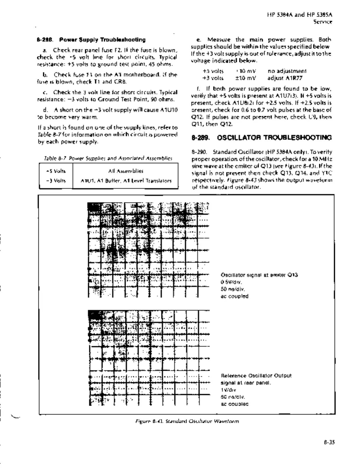
8-290. Standard Oscillator (HP 5384A only).
To
verify
proper
operation
of
the
oscillator, check
for
a
10
MHz
sine wave at
the
em
iter
of
Q13
(see
Figure 8-43). If the
signal
is
not
present
then
check Q13, Q14, and
Y1C
respectively. Figure 8-43 shows
the
output
waveform
of
the
standard oscillator.
Oscillator
signal at
emiter
013
0.5VIdiv.
50
ns/div.
ac
coupled
Reference
Oscillator
Output
signal
at
rear panel.
1 Vldiv.
50
ns/div.
ac
coupled
Figure
8-43.
Standard Oscillator Waveform
8-35