•
•
•
DISPLAY DIGITS
'---
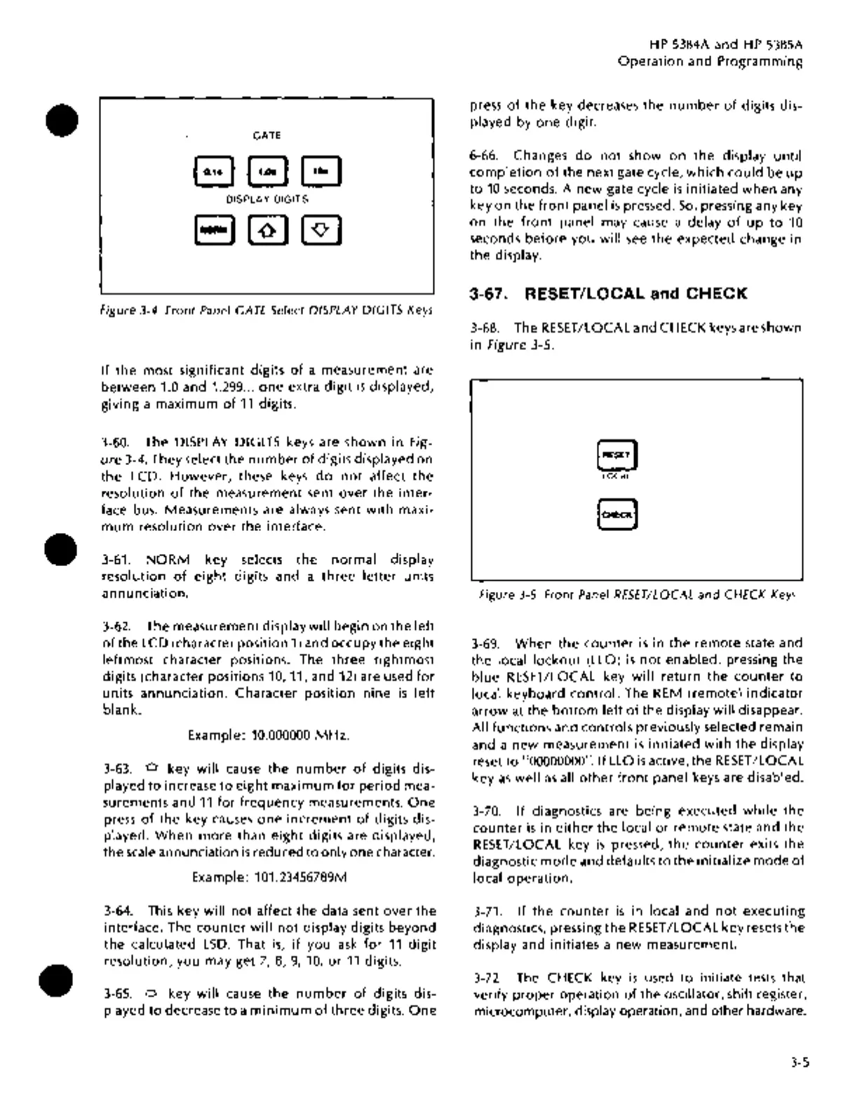
Figure
3-4.
Front
Panel GATE Select DISPLAY
DIGITS
Keys
If
the most significant digits
of
a measurement are
between
1.0 and 1.299 ...
one
extra
digit
is
displayed,
giving a
maximum
of
11
digits.
3-60. The
DISPLAY
DIGITS keys are shown
in
Fig-
ure
3-4. They select
the
number
of
digits displayed
on
the LCD.
However,
these keys
do
not
affect
the
resolution
of
the
measurement sent over
the
inter-
face bus. Measurements are always sent
with
maxi-
mum
resolution
over
the
interface .
3-61.
NORM
key selects
the
normal
display
resolution
of
eight
digits and a
three
letter
units
annunciation.
3-62.
The measurement display
will
begin
on
the
left
of
the LCD (character position
1)
and
occupy
the
eight
leftmost character positions. The
three
rightmost
digits (character positions 10, 11, and
12)
are used
for
units annunciation. Character position
nine
is
left
blank.
Example: 10.000000
MHz.
3-63.
o key
will
cause
the
number
of
digits dis-
played
to
increase
to
eight
maximum
for
period
mea-
surements and
11
for
frequency
measurements.
One
press
of
the key causes
one
increment
of
digits dis-
played.
When
more
than
eight
digits are displayed,
the
scale
annunciation
is
reduced
to
only one character.
Example: 101.23456789M
3-64.
This key
will
not
affect the data sent
over
the
interface. The
counter
will
not
display digits beyond
the
calculated
LSD.
That
is,
if
you
ask
for
11
digit
resolution, you may get
7,
8,
9,
10,
or
11
digits .
3-65.
o key
will
cause
the
number
of
digits dis-
played
to
decrease
to
a
minimum
of
three
digits.
One
HP
5384A and
HP
5385A
Operation
and Programming
press
of
the
key decreases the
number
of
digits dis-
played by
one
digit.
6-66. Changes
do
not
show
on
the
display
until
completion
of
the next gate cycle,
which
could
be
up
to
10
seconds. A new gate cycle
is
initiated
when
any
key
on
the
front
panel
is
pressed.
So,
pressing any key
on
the
front
panel may cause a delay
of
up
to
10
seconds
before
you will
see
the expected change in
the
display.
3-67. RESET/LOCAL and CHECK
3-68. The RESET/LOCAL and CHECK keys are shown
in
Figure 3-5.
B
lOCAl
EJ
Figure
3-5.
Front
Panel RESET/LOCAL
and
CHECK
Keys
3-69.
When
the
counter
is
in
the
remote
state and
the
local
lockout
(LLO)
is
not
enabled, pressing the
blue
RESET/LOCAL key
will
return
the
counter
to
local keyboard
control.
The
REM
(remote)
indicator
arrow
at
the
bottom
left
of
the display
will
disappear.
All functions and controls previously selected remain
and a
new
measurement
is
initiated
with
the
display
reset
to
"00000000". If LLO
is
active, the RESET/LOCAL
key
as
well
as
all
other
front
panel keys are disabled.
3-70.
If
diagnostics are being executed
while
the
counter
is
in
either
the local
or
remote
state and
the
RESET/LOCAL key
is
pressed,
the
counter
exits
the
diagnostic
mode
and defaults
to
the
initialize
mode
of
local
operation.
3-71.
If
the
counter
is
in local and
not
executing
diagnostics, pressing
the
RESET
/LOCAL
key resets
the
display and initiates a
new
measurement.
3-72.
The CHECK key
is
used
to
initiate tests that
verify
proper
operation
of
the oscillator, shift register,
microcomputer,
display operation, and other hardware.
3-5