•
•
•
the
Hewlett-Packard Interface
Bus
(H
P-1
B)
or
the
Hewlett-Packard Interface
Loop
(HP-IL).
Option
003
is
HP-IL.
3-84. The interface address switch (ADDR)
is
a
seven-position switch that
is
used
to
manually set
the
remote
control
address
of
the
counter.
The five
rightmost
switch positions are externally accessible
and can be used by
the
operator
for
setting
the
address. The
two
leftmost
switch positions are
not
used
for
normal
operation.
For a
complete
descrip-
tion
of
address selection,
refer
to
Table 3-4, Address
Selection,
in
the
Remote
Programming
Instructions in
this section.
3-85. The
HP-IB and HP-IL capabilities
of
the
counter
are listed above
the
interface
port.
For a
complete
de-
scription
of
the
listed capabilities, refer
to
paragraph
3-118,
Interface Commands.
3-86. The AC
LINE INPUT
connector
accepts
the
ac
input
power
cord. The
protective
grounding
con-
ductor
also connects
to
the
instrument
through
the
ac
power
connector.
3-87. The LINE
SELECT
switch selects
the
instrument
line
voltage. The switch selects
either
115
or
230
volts.
The
number
visible
on
the
switch indicates
the
nominal
line
voltage
to
which
the
instrument
must be
connected
for
proper
operation.
3-88. The DC
FUSE
is
a
two-ampere
fast-blow fuse
for
the
protection
of
the
de
power
supply
to
the
instrument. The de fuse
is
the
main
protection
for
the
counter.
The fuse value should be
two
ampere 3AG
fast-blow.
3-89. The
EXT
DC INPUT
power
connector
accepts
the
two
conductor
de
input
power
cable.
Input
volt-
age range
is
from
9 volts
to
15
volts de and 1.0 ampere
maximum. The
EXT
DC INPUT
is
fuse
protected
for
a
2.0
ampere surge
current.
3-90. The
10
MHz
IN/OUT
BNC
connector
provides
a
10
MHz
signal that may be used
for
calibration
when
the
INT
EXT
switch
is
in
the
INT position.
When
the
INT
EXT
switch
is
in
the
EXT
position,
the
IN/OUT
BNC
connector
becomes
the
external reference
input
for
the
counter.
3-91. EXTERNAL
DC
OPERATION
3-92. For external de
operation,
connect
the
de
power
cable
to
the
EXT
DC INPUT
connector.
Con-
nect
the
other
end
to
a de
power
source
of
9-15 volts
and
500
mA
minimum.
If
Option
005
battery pack
is
installed,
the
external de
power
source should
provide
a
minimum
de
current
of
700
mA
to
allow
for
battery
charging.
HP
5384A and HP 5385A
Operation
and
Programming
3-93.
MAKING
FREQUENCY
AND
PERIOD
MEASUREMENTS
I
WARNING
I
DURING
BATTERY
OPERATION
WITH
THE
MAINS POWER CORD DISCONNECTED FROM
THE
MAINS
SUPPLY,
THE
FRONT AND
REAR
PANELS
WILL
FLOAT
ATTHEVOLTAGEAPPLIED
TO
SIGNAL
COMMON
(INPUT
BNC
CON-
NECTOR
SHELL).
TO AVOID
THE
RISK
OF
ELECTRIC
SHOCK DURING
BATTERY
OPER-
ATION,
ENSURE
THE
VOLTAGE
APPLIED
TO
SIGNAL
COMMON
(BNC
SHELL)
DOES NOT
EXCEED
42V
PEAK.
3-94. The
recommended
sequence
for
setting-up
and
making
a measurement
with
the
HP
5384A
or
HP
5385A Frequency
counter
is
given
below.
a.
Set
the
power
switch
to
ON.
The
counter
should
perform
a
power-up
self-check,
then
preset
to
the
power-up
initialize
settings
shown
in Table 3-1.
b.
Press
the
key
for
the
desired
operating
mode
(frequency,
period
etc.).
c.
Connect
a signal
into
the
channel selected.
d.
If
the
display
is
unstable, use
the
attenuator,
filter,
or
manual
trigger
level
control
and adjust
for
a
stable reading. The above
mentioned
controls
have
limitations. They
cannot
compensate
for
excessively
noisy
or
unstable signal sources.
e.
If
desired, select a gate
time
and
the
number
of
display digits desired.
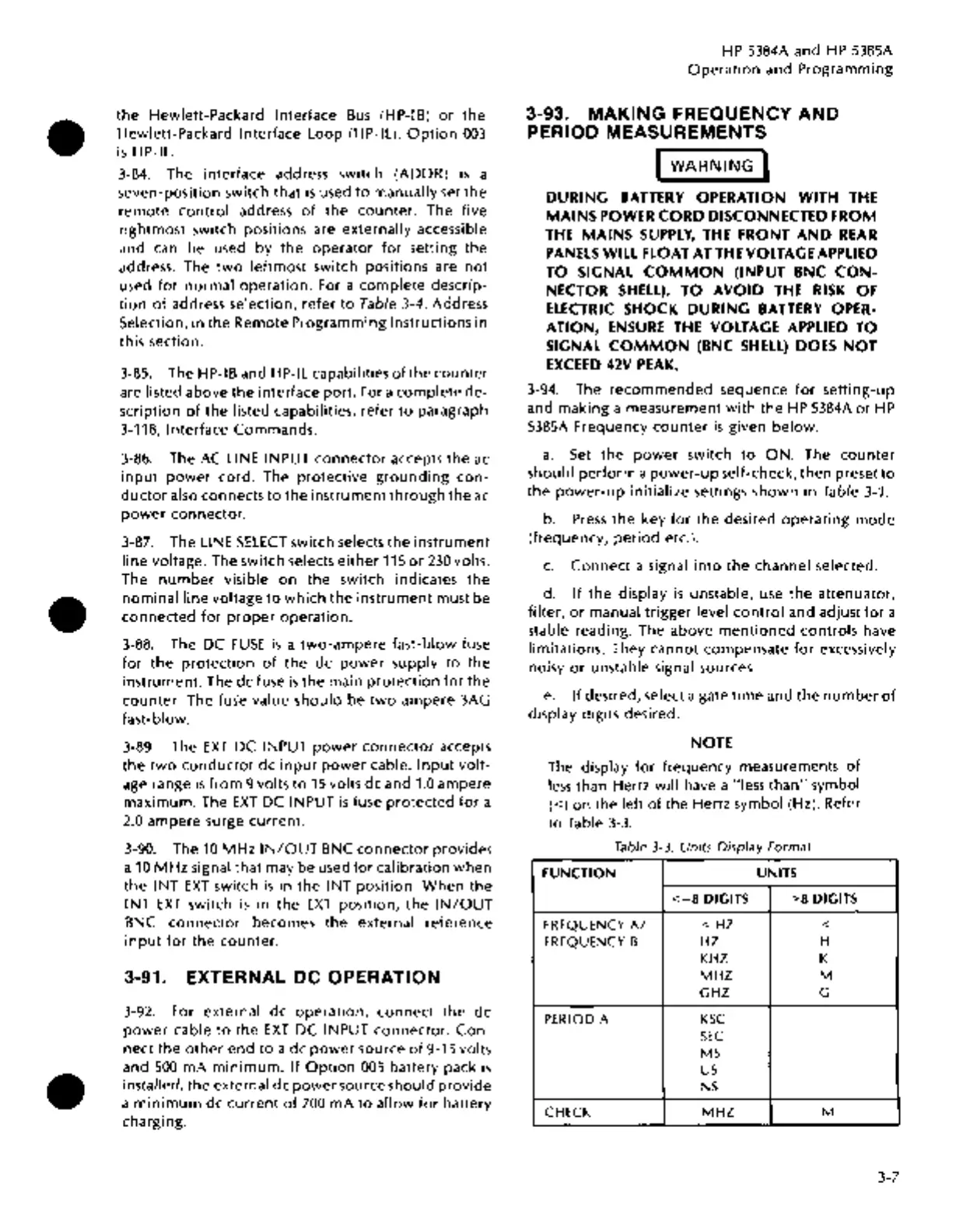
NOTE
The display
for
frequency measurements
of
less
than Hertz will have a "less
than"
symbol
(<)on
the left
of
the Hertz symbol (Hz). Refer
to
Table
3-3.
Table 3-3. Units Display Format
FUNCTION
UNITS
<=8
DIGITS
>8
DIGITS
FREQUENCY
AI
<HZ
<
FREQUENCY
B
HZ
H
KHZ
K
MHZ
M
GHZ G
PERIOD A
KSC
SEC
MS
us
NS
CHECK
MHZ
M
3-7