HP
5384A and
HP
5385A
Service
8-198. The
Multiple
Register
Counter
(MRC), a
counter
on
a
chip,
is
an
lSI
bipolar
IC
utilizing
both
EFland
12l
circuitry. The reference oscillator drives
the
MRC
via
pin
21.
The reference oscillator may be
monitored
at
TP3
located on the A 1
Motherboard.
Inputs
from
channels A and
Bare
fed
into
the
MRC
at
pins
30
and
28
respectively.
8-199.
Within
the
MRC
are
four
addressable regis-
ters. The Events Register and Time Register are
counting
registers; thus
they
are Read
Only.
The
Status Register
monitors
the
operation
of
the
MRC,
and
the
Control
Register receives
the
commands
from the
3870
and determines the MRC's configuration.
8-200. Interpolator Technique
8-201. A major feature
of
the
HP
5384A and
HP
5385A
is
the
pulse
count
interpolators.
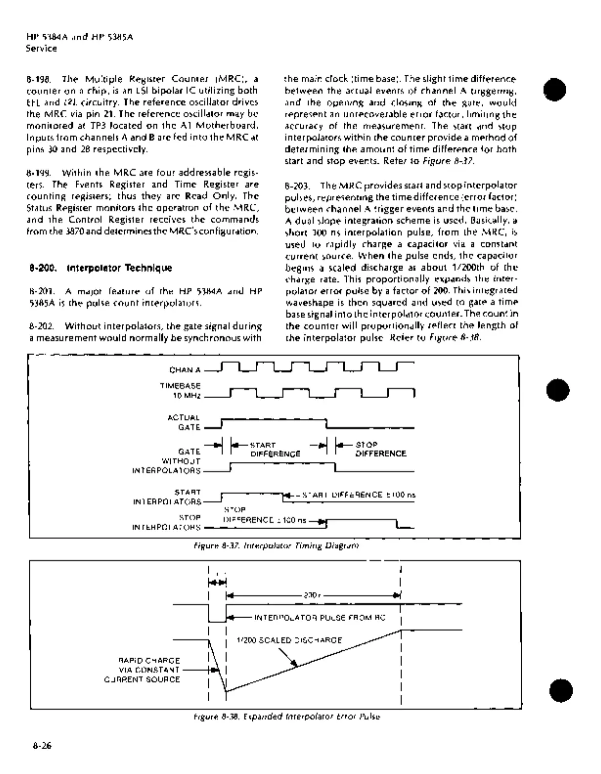
8-202.
Without
interpolators, the gate signal
during
a measurement
would
normally
be synchronous
with
CHAN A
TIMEBASE
10
MHz
ACTUAL
GATE
the
main clock (time base). The slight
time
difference
between
the
actual events
of
channel A triggering,
and
the
opening
and closing
of
the
gate,
would
represent
an
unrecoverable
error
factor,
limiting
the
accuracy
of
the
measurement. The start and stop
interpolators
within
the
counter
provide
a
method
of
determining
the
amount
of
time
difference
for
both
start and stop events. Refer
to
Figure 8-37.
8-203. The
MRC
provides start and stop
interpolator
pulses, representing
the
time
difference
(error factor)
between
channel A
trigger
events and the
time
base.
A
dual
slope
integration
scheme
is
used. Basically, a
short
100
ns
interpolation
pulse,
from
the
MRC,
is
used
to
rapidly
charge a capacitor via a constant
current
source.
When
the
pulse ends,
the
capacitor
begins a scaled discharge at
about
1/200th
of
the
charge rate. This
proportionally
expands
the
inter-
polator
error
pulse by a factor
of
200.
This integrated
waveshape
is
then squared and used
to
gate a
time
base signal
into
the
interpolator
counter.
The
count
in
the
counter
will
proportionally
reflect the
length
of
the
interpolator
pulse. Refer
to
Figure 8-38.
_-1
'--sTART
GATE
I I DIFFERENCE
WITHOUT
INTERPOLATORS
__j
_-1
'--sTOP
I I DIFFERENCE
8-26
START
INTERPOLATORS
__j
STOP
1'4:-START
DIFFERENCE±
100 ns
STOP
INTERPOLATORS
DIFFERENCE ± 100 ns =:!!
Figure
8-37.
Interpolator
Timing Diagram
L
I
+I
I
~
I
I
,...l.,........_----2oo+------t..,~l
LJ4=
INTERPOLATOR PULSE FROM
RC
I I
---.I
RAPID CHARGE I
VIA
CONSTANT--~
I
CURRENT SOURCE
Figure
8-38.
Expanded
Interpolator
Error Pulse
I
I
•
•
•